e30bj662.11
17
15
7
3
5
2
1
9
8
6
4
13
11
10
16
14
12
18
Ref+
Ref–
Sin+
Sin–
Cos
Cos–
1
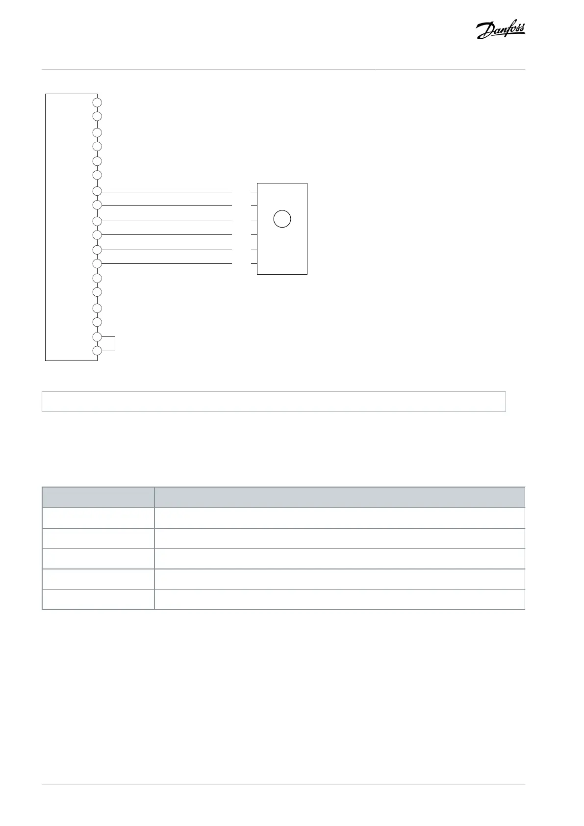
Illustration 9: Wiring Configuration for Resolver
5.5.4 Resolver with Mirror Out
When using a resolver, a TTL encoder signal can be generated to mirror the resolver signal. The mirroring enables transferring the
shaft position to other devices for monitoring or further control. The encoder output signal can be scaled by defining the number of
pulses representing 1 rotation of the resolver.
Table 11: Parameters for Resolver with Mirror Out
9.4.1 Interface Configuration
Select [8] Resolver A,B + Mirror out Z,D.
9.5.2 Resolution Channel 2
Set the required number of pulses for the encoder output representing 1 rotation of the resolver.
Set the excitation voltage according to the resolver specifications.
9.7.2 Excitation Frequency
Set the excitation frequency according to the resolver specifications.
Set the number of poles for the connected resolver.
AQ390830267692en-000601 / 136R027322 | Danfoss A/S © 2023.06
Encoder/Resolver Installation and
Configuration
Functional Extension Options
Operating Guide