8
6
4
13
11
10
16
14
12
18
Sin+
Sin–
Cos+
Cos–
Ref+
Ref–
A+
A–
B+
B–
1
2
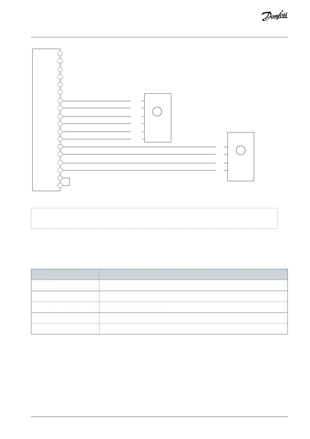
Illustration 10: Wiring Configuration for Resolver with Mirror Out
Controller or other device
5.5.5 Resolver and Incremental (TTL) Encoder
This example of a resolver on A and B as channel 1 and a 2-track incremental TTL encoder on Z and D as channel 2. The internal
supply of the option is used for resolver excitation. The encoder supply (pin 17) is inactive, so the incremental encoder must be
supplied by an external power source.
Table 12: Parameters for Resolver and Incremental (TTL) Encoder
9.4.1 Interface configuration
Select [9] Resolver A,B + 2 track incremental Z,D.
9.5.2 Resolution Channel 2
Set the resolution of the encoder connected to Z and D in pulses per revolution.
Set the excitation voltage according to the resolver specifications.
9.7.2 Excitation Frequency
Set the resolver excitation frequency according to the resolver specifications.
9.7.3 Number of Pole Pairs
Set the number of pole pairs for the connected resolver.
AQ390830267692en-000601 / 136R0273 | 23Danfoss A/S © 2023.06
Encoder/Resolver Installation and
Configuration
Functional Extension Options
Operating Guide