User Guide | Intelligent Purging System (IPS 8) for Ammonia - Technical data, installation and use
© Danfoss | DCS (ms) | 2020.01
BC306932151284en-000201 | 15
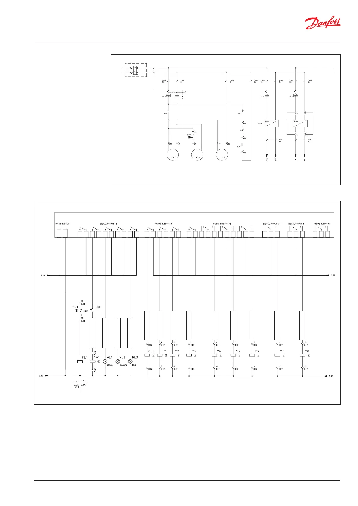
Electrical wiring
(continued)
Fig. 17 Power Supply
*When using GD2 24V DC, remove 1-2 and 3-4 bridges between the terminals and connect power supply
Fig. 18 Controller MCX15B Inputs and Outputs
L/1
N/1
L
N
L/3
L/4
L/5
9
8
L/2
Compressor
M1 M2 VR1
1 1 1
Press.
Switch
Extraction
air fan
Crankcase
heater
24V DC
0V DC
Power supply
MCX15B
Power supply
Solenoid valves*
Condenser
Fan
230V AC
QS1
QM1 QM2
GD1 GD2
QM3
KL1 KL1
TR
RC
NO 1
C 1
NO 2
C 2
NO 3
C 3
NO 4
C 4
NO 5
C
5
N1
L 1
NO 6
C 6
NO 7
C 7
NO 8
C 8
NO 9
C 9
NC 15
C 15
NO 15
NC 14
C 14
NO 14
NC 13
C 13
NO 13
NC 12
C 12
NO 12
NC 11
C 11
NO
11
NC 10
C 10
NO 10
9
8
12
3
4
5
6
7
10
11
12
13
14
17
18
15
16
Solenoid valve
System running
System running
System error
Solenoid valve
Solenoid valve
Solenoid valve
Solenoid valve
Solenoid valve
Solenoid valve
Solenoid valve
Solenoid valve
Solenoid valve
24V DC
0V DC
MCX15B OUTPUT
 Loading...