User Guide | Intelligent Purging System (IPS 8) for Ammonia - Technical data, installation and use
6 | BC306932151284en-000201
© Danfoss | DCS (ms) | 2020.01
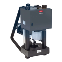
Working principle The Danfoss IPS 8 is factory-tested and ready to
use in ammonia plants with a condenser pressure
of more than 6,5 bar (94 psi). The purger is
charged with 900 gram (31.7 oz) of R452A.
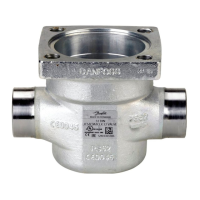
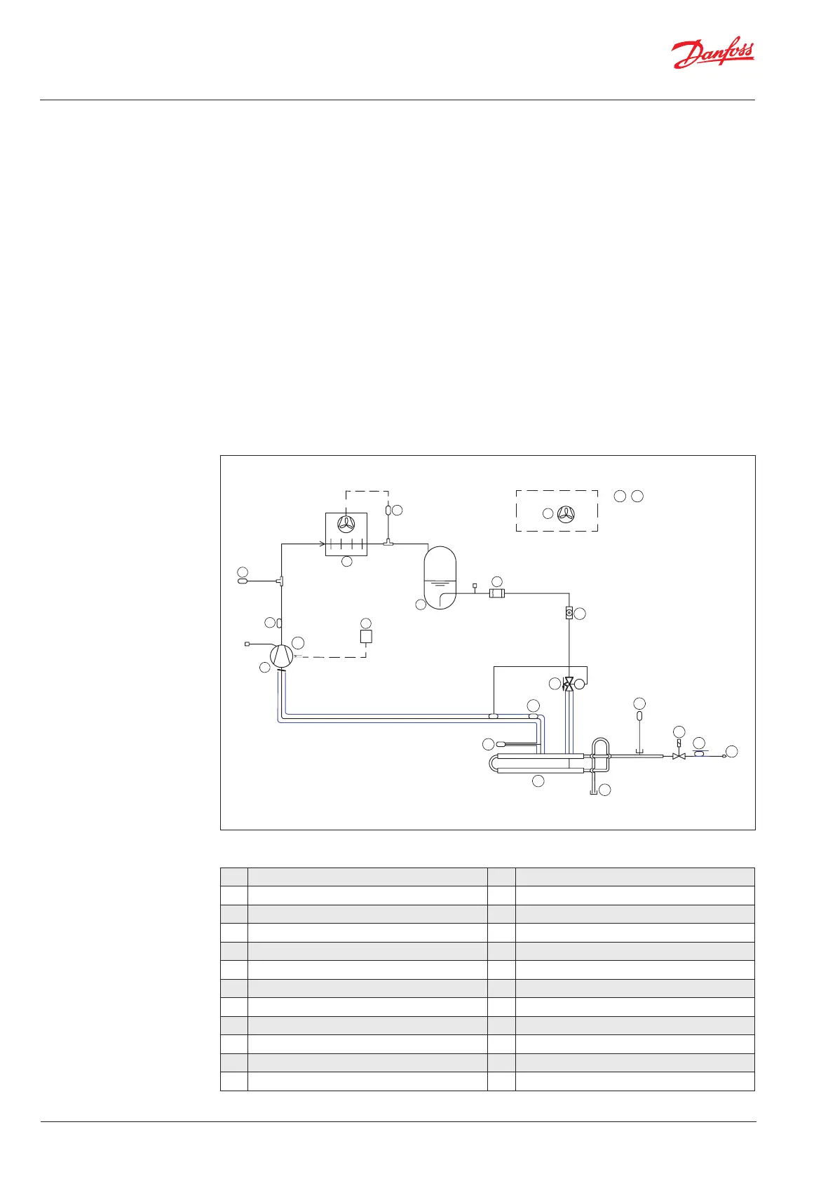
Only 2 mechanical connections are needed for
the purger (see fig. 1). The flow of ammonia/NC
gases from the main plant is done through the
flange for ammonia (see 13 in Fig. 1 below), while
the NC gas purge is done through the blow-off
pipe after the purge restrictor (18).
Through the flange for ammonia (13), a mixture
of ammonia gas and NC gases enters the heat
exchanger (12) part of the purger.
The ammonia gas/NC gas mix is cooled down
below the condensing temperature of the
ammonia by the R452A circuit. At this point,
ammonia gas condenses and returns by gravity
to the ammonia plant whereas the NC gases
accumulate in the heat exchanger (12) for
subsequent purging.
By condensing the ammonia gas, a new
ammonia/NC gases mix is naturally pulled
through. This new mix is separated through a
continuous process.
As the NC gas concentration in the heat
exchanger (12) increases, the R452A heat
exchanger pressure and temperature will
simultaneously decrease.
The controller continuously monitors the R452A
heat exchanger pressure as well as ammonia
pressure and temperature. When the R452A
pressure reaches a predefined pressure difference
when compared with the ammonia pressure
(temperature) it prepares to purge the NC gases
through the solenoid valve (16). The blow-off
is activated by the solenoid (16) and through
appropriate piping/hosing, should be led into
a water bath. This process is recommended
to retain small amounts of ammonia (see
Installation section).
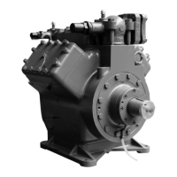
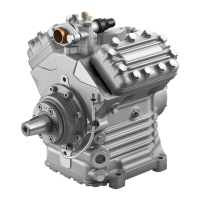
1 Compressor R452A 11 Expansion valve, R452A
1a Compressor Cranck case heater 12 Heat exchanger Ammonia/R452A
2 Thermostat for crankcase heater control 13 Welding Flange
3 Discharge temp sensor R452A 14 Pressure transmitter R452A
3a Suction temperature sensor R452A 15 Pressure transmitter R717
4 Pressure safety switch 16 Solenoid valve AKVA and coil
5 Condenser 17 NC temperature sensor R717
6 Extraction fan 18 Restrictor, purge line
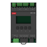
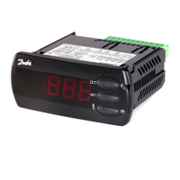
7 Pressure switch for Fan 19 MCX 15 (Pre-programmed)
8 Receiver 20 PSU, 24V
9 Filter 900 gram (31.7 oz) R452A
10 Sight glass
Fig. 1 - Purger R452A lay-out
1
1a
2
3
4
5
7
8
9
10
11
15
16
17
18
12
14
6
19 20
3a