User Guide | Intelligent Purging System (IPS 8) for Ammonia - Technical data, installation and use
14 | BC306932151284en-000201
© Danfoss | DCS (ms) | 2020.01
Electrical wiring
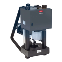
The internal wiring of the purger is done at the
factory. Only the electrical wiring for the main
power supply, the purge point solenoids and
optional bus communication needs wiring on site.
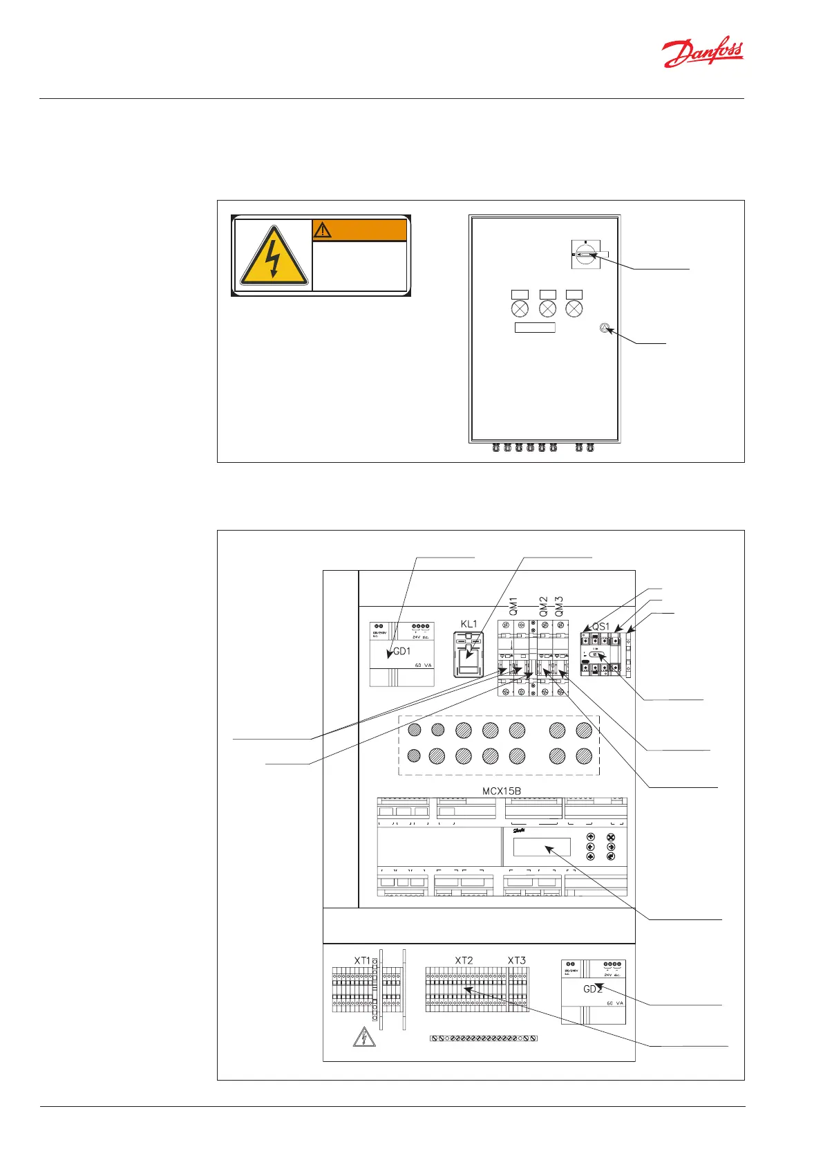
Controller box cover can only be opened at key unlock and with the main switch off.
Note: Authorized personel only
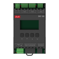
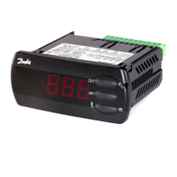
Fig. 15 Controller box external
Fig. 16 Controller box internal
It is highly recommended that all external cables
coming from the IPS 8 to the power supply and
to all purge point solenoids are protected by
metallic pipes.
Electrical
hazards.
Authorized
personnel only.
WARNING
ON/OFF Switch
STANDBY
RUN ERROR
PURGING
Key Lock
COM
AI1
AI2
ANALOG INPIT 1-6
COM
AI7
AI8
AI9
AI10
5V+
ANALOG INPUT 7-10
DI 2H
DI 2
COM
DIGITAL INPUT 2
CAN
CAN RJ
MCX
DI 3H
DI 3
COM
DIGITAL INPUT 3
DI 4H
DI 4
COM
DIGITAL INPUT 4
AO5
COM
ANALOG OUTPUT 5-6
DIGITAL OUTPUT 15
AI3
5V+
12V+
5V+
AI4
AI5
L
N
POWER
DI 17
DI 18
COM
COM
DIGITAL INPUT 17-18
DI 13
DI 14
DI 16
COM
DIGITAL INPUT 13-16
DI 15
DI 9
DI 10
DI 12
COM
DIGITAL INPUT 9-12
DI 11
DI 5
DI 6
DI 8
COM
DIGITAL INPUT 5-8
DI 7
AO6
COM
DI 1
D1 H
DIGITAL INPUT 1DIGITAL OUTPUT 14
NO 14
COM
NC 14
NO 15
COM
NC 15
AI6
COM
MCX15B Controller
Up to 8 purge valves
Optional 24V DC
power supply for (8)
purge solenoids
(not included)
MCX15B Controller
On/Off
Main Switch
Main Power
230V 50 Hz
L
Compressor relay24V Converter
Compressor/condenser
fan On/Off
Purge valve
Earth
N
Solenoid valves
On/Off