User Guide | Intelligent Purging System (IPS 8) for Ammonia - Technical data, installation and use
© Danfoss | DCS (ms) | 2020.01
BC306932151284en-000201 | 19
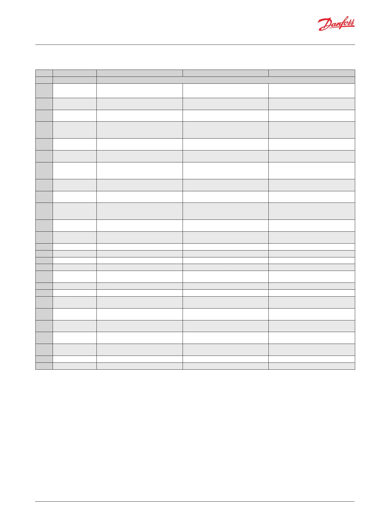
Label Parameter Name Description Possible Reason Recommended action
ALARMS
A01 General alarm Input from AI3 Leads to shut down of IPS 8 Fault in system connected to the DIO4 Input from AI3 Leads to shut down of IPS 9
E01 Temp Sensor Fault
Indicates no signal from temperature sensor
(R452a)
Broken wire to R452a temperature sensor
Repair temperature sensor wire or replace
temperature sensor
E01 Temp Sensor Fault
Indicates no signal from temperature sensor
(R452a)
Electrical supply failure supplying R452a
temperature sensor
Repair or replace power source
E01 Temp Sensor Fault
Indicates no signal from temperature sensor
(R452a)
Temperature measurement of the R452a line
is out of range
Compare temperature with another
temperature sensor reading and replace
temperature sensor if needed
E02 BPL Sensor Fault
Indicates no signal from pressure transmitter
(R452a)
Broken wire to R452A pressure transmitter
Repair pressure transmitter wire or replace
pressure transmitter
E02 BPL Sensor Fault
Indicates no signal from pressure transmitter
(R452a)
Electrical supply failure to the R422a pressure
transmitter
Repair or replace power source
E02 BPL Sensor Fault
Indicates no signal from pressure transmitter
(R452a)
Pressure measurement of the R452a line is out
of range
Compare pressure with another pressure
reading and replace pressure transmitter if
needed
E03 BPL Sensor Fault
Indicates no signal from pressure transmitter
(R717)
Broken wire to R717 pressure transmitter
Repair pressure transmitter wire or replace
pressure transmitter
E03 BPL Sensor Fault
Indicates no signal from pressure transmitter
(R717)
Electrical supply failure to the R717 pressure
transmitter
Repair or replace power source
E03 BPL Sensor Fault
Indicates no signal from pressure transmitter
(R717)
Pressure measurement of the R717 line is out
of range
Compare pressure with another pressure
reading and replace pressure transmitter if
needed
E04 Low temperature
Indicates too low ambient temperature
(<-10 °C)
Too low ambient temperature Move the IPS to a higher ambient temperature
E05 High temperature
Indicates too high ambient temperature
(>120 °C)
Too high ambient temperature Move the IPS to a lower ambient temperature
E05 High temperature Low R452a charge because of possible leak Locate and repair leak Evacuate Move the IPS to a lower ambient temperature
E06 Low pressure BPL Indicates too low R717 pressure Closed stop valve Open inlet stop valve
E07 High pressure BPL Indicates too high R717 pressure Ammonia system pressure too high Wait for lower pressure
E08 Low pressure BPH Indicates too low R452a pressure Low R452A charge
Find and repair leak, evacuate and recharge
with R452a
E09 High pressure BPH Indicates too high R452a pressure R452s system pressure too high Wait for lower pressure
E10 System is OFF Indicates status of the main switch Main switch is OFF Switch ON the main switch
E11 Memory is full A memory reset is required Memory is full from long time operation
Clean MCX memory by means of finding
Parameters_UnitConfig_
E12 Totla purge time error
This occurs when PLT is activated System will
automatically restart when CST has expired
Restrictor is blocked Replace the restrictor
E13 Compressor ERROR
Indicates no status is being received from
relay KL01
Possible broken wire from the MCX Repair broken wire from the MCX
E14 Liquid alarm
Signal from the LLS that there is liquid in the
evaporator
E15 Memory wrong!
Wrong counter values The unit will
automatically repair itself
E16 Discharge sensor error Indicates no signal from temperature sensor
E17 Suction sensor error Indicates no signal from temperature sensor
Table 03
Occurring active alarms, possible reasons and recommended action
All alarms except (*) activates red light on box outside
For alarms not resettable and/or cause not identified, please contact Danfoss
Level legend: 0 = Read view, 2 = Installer view (code 200) 3 = Danfoss Service view (Contact Danfoss)