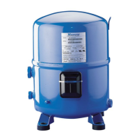
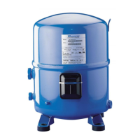
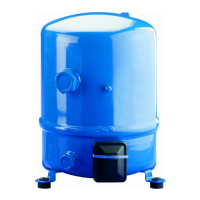
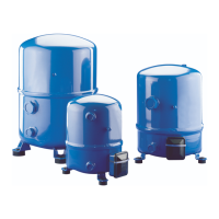
RECIPROCATING COMPRESSORS
15 kΩ - 1 W
230 V
"A + C"
B µF
5
Start Relay
2
1
S R
C
220 kΩ - 1 W
IOL
PTC
FU
FU
C1
EC
TH
N
L1
L2
L3
C1
MS
IOL
Comp.
10
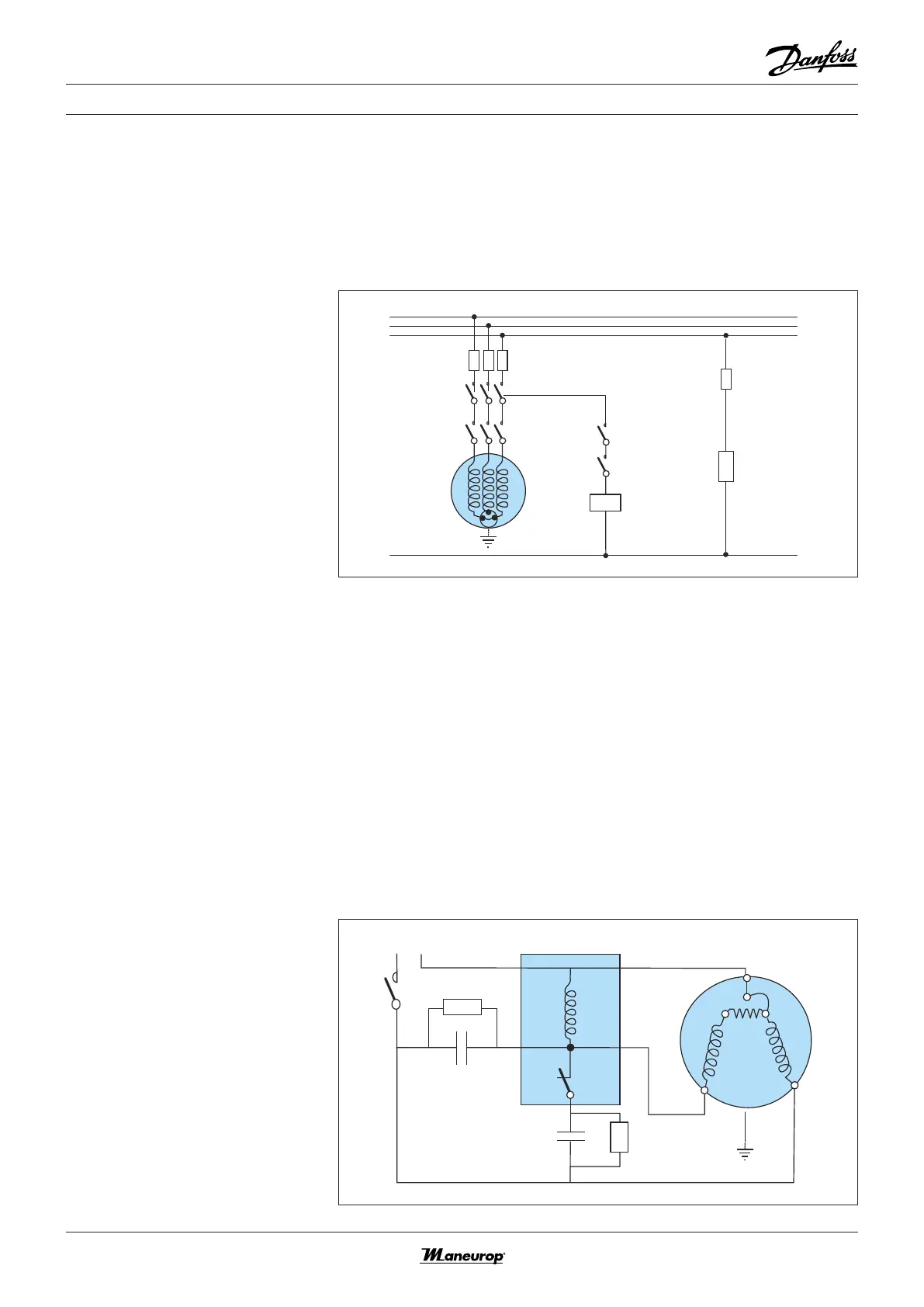
ELECTRICAL CONNECTIONS AND WIRING
Three phase motor
protection and
suggested wiring
diagram
Three phase compressors are inter-
nally protected by a temperature /
current-sensing bimetallic protector,
connected to the neutral point of
the star-connected stator windings.
This internal overload line break pro-
tects the motor against overheating,
current overload and locked rotor
conditions. If the motor were to be
overloaded and the protector trips, all
3-phases are cut out. It might take up
to several hours to reset and restart
the compressor.
Single phase motor
protection and
suggested wiring
diagram
Single phase electrical characteristics
and capacitor and relay data are not
Single phase compressor motors are
internally protected by a temperature
/ current-sensing bimetallic protector
which senses the main and start win-
ding current as well as motor winding
temperature. If the motor were to be
overloaded and the protector trips, it
might take up to several hours to reset
and restart the compressor.
The standard CSR wiring system pro-
vides additional motor torque at start-
up, by the use of a start capacitor in
combination with a run capacitor.
The start capacitor is only connected
during the starting operation and a
potential relay disconnects it after the
start sequence. This sytem can be used
for refrigerant circuits with capillary
tubes or expansion valves.
Single phase electrical
characteristics
available at the publication date of
this document.
FU Fuses
MS Main switch
C1 Compressor contactor
TH Thermostat
EC External controls
COMP Compressor
PTC Crankcase heater
IOL Internal overload line break
IOL Motor protector
A + C Run capacitors
B Start capacitor
C Common
S Start winding (auxiliary)
R Run winding (main)
Capacitors A and C are replaced by a single ca-
pacitor of size A + C
 Loading...