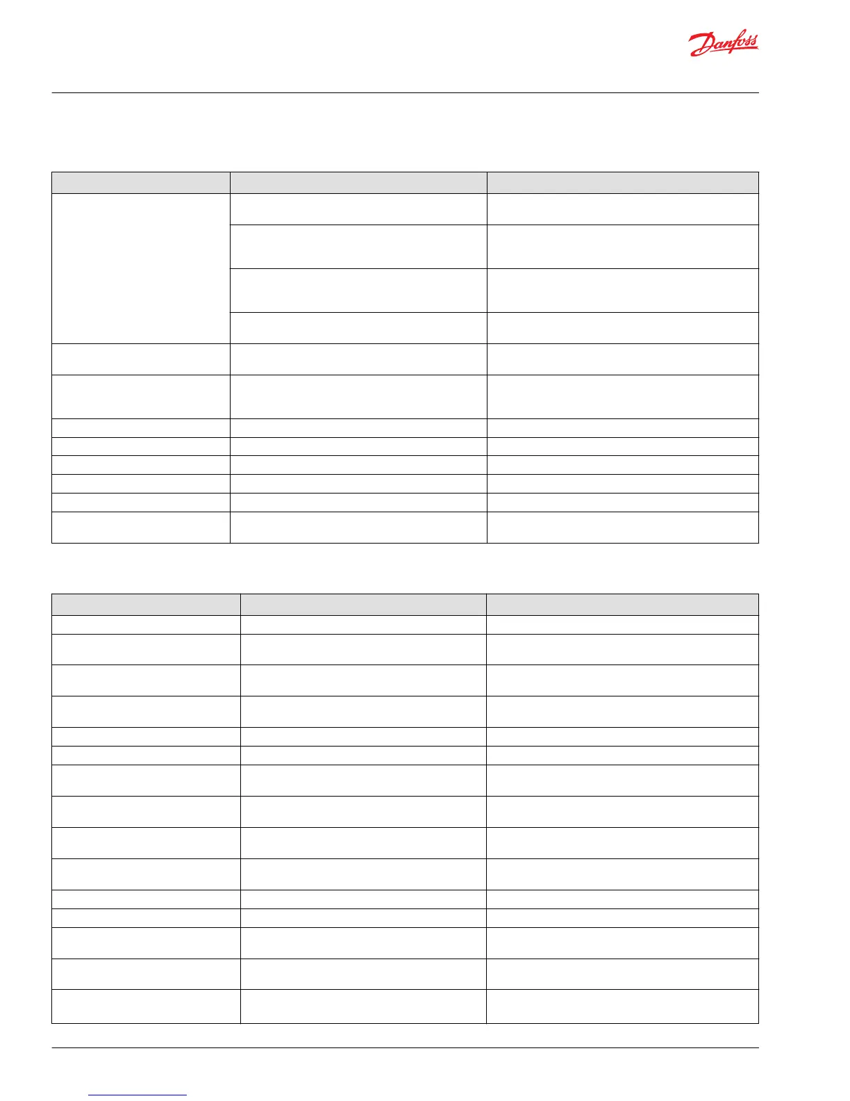
Cylinder/motor responds in one direction only
Cause Check Corrective action
Verify if fault is mechanical, electrical
or hydraulic
Operate manual lever in both directions to confirm if
mechanical or electrical or hydraulic
If moving the manual lever operates the cylinder/motor
in both directions check electrical or hydraulic
If operating the manual lever strokes the cylinder/
motor in one direction only, check manual stop screw
adjustment
Back out manual stop on manual controller and torque
the jam not to 8 Nm [70 lbf•in] Do not exceed maximum
torque
Check movement of manual lever when electrical
controller is operated
If manual lever does not move in one direction check
electrical signal from controller and wiring at the PVE
module
Check movement of manual lever when hydraulic
controller is operated
If manual lever does not move in both directions check
hydraulic pressure at the PVG module
Air in system Entrained air generates heat under pressure Look for foam or bubbles in reservoir. Check for leaks on
inlet side of charge pump.
Internal leakage Excessive internal leakage may overheat the system. Install loop flushing defeat option and monitor case flow.
If case flow is excessive, motor may require major repair.
Contact Danfoss Service.
Shock valves Swap and see if problem follows Replace valves
Solenoid actuation If power is OK from controller Repair wiring to PVE module
Main spool travel restricted Stop on manual controller turned in too far Back out manual stop on manual controller
Remote electrical controller Insufficient signal from electrical controller Repair or replace electrical controller
PVEO connections Incorrect PVE/PVEO connections Connect correct way
Remote hydraulic controller PVRH Insufficient pilot oil pressure from remote hydraulic
controller Pressure needs to be 25 Bar [360 psi]
Repair or replace remote hydraulic controller
Main valve spool moves without oil passing to cylinder/motor
Cause Check Corrective action
Insufficient oil supply to valve Check the pump per manufacturers procedure Repair or replace pump per manufacturers procedure
Optional pressure compensator in
valve section not functioning
Check compensator spool Replace spool
Insufficient load pressure at
compensator spring chamber
LS drilling holes plugged Clean or replace
Cylinder/motor load too high for
pressure setting of the system
Check pressure at the valve If pressure is set to spec. per valve lower load on cylinder/
motor
Blocked LS galleries Inspect for blockage in LS galleries Remove blockage in LS galleries
Shuttle valve faulty Inspect shuttle valve Repair or replace
Blocked LS lines to pump controller Inspect LS lines from PCG to pump controller Remove blockage in LS lines from the PVG valve to pump
controller
Oil bypassing at shock valve/anti-
cavitation check valve
Check if stuck open or damaged Replace valve
Internal leakage in cylinder/motor Inspect for by-passing of oil per cylinder/motor
manufacture per manufactures procedure
Repair or replace cylinder/motor per manufactures
procedure
Too much leakage in LS spool in pump
control
Check bleed orifice in LS control Use a LS pump control with no bleed orifice
Blocked thermal orifice check thermal orifice (blocked) Replace thermal orifice
Load too high for system Check for proper system pressure Adjust pressure to valve specification
Internal leakage in cylinder/motor Inspect for bypassing of oil per cylinder/motor
manufacturer specification
Repair or replace cylinder/motor
Shock valve or anti-cavitation check
valve faulty
Inspect for damage and contamination Repair or replace cylinder/motor
System relief valve pressure set too low
for load
Install pressure gauge and check pressure
Adjust pressure to system specification
Lower load
Service Manual
PVG 32 Proportional Valve Group
System Troubleshooting
16 |
©
Danfoss | February 2017 11039167 | AX00000031en-US0301

 Loading...


