7 | © Danfoss | Energy Meters | 2020.11 BC200586470576en-020601
Installation guide SonoMeter 30
1.6. Setting up the jumpers (J)
The connector J is on the calculator plate between the temperature sensors and pulse input / output con-
nection terminals (see 6.3). Joining or leaving open the connector contacts, you can choose the normal or
verification (test) mode, activate the pulse inputs or outputs:
Jumper is not set
(contacts are opened)
Jumper is set
(contacts are connected)
NORMAL MODE VERIFICATION (TEST) MODE
The first pulse output V1 is active
(terminals 52,53).
Energy as default.
The first pulse intput V1 is active
(terminals 52,53)
(Jumper must be removed when
operating in TEST mode)
The second pulse output V2 is active
(terminals 50,51).
Volume as default.
The second pulse intput V2 is active
(terminals 50,51)
(Jumper must be removed when
operating in TEST mode)
Note: On delivery the heat meter is configured with two outputs.
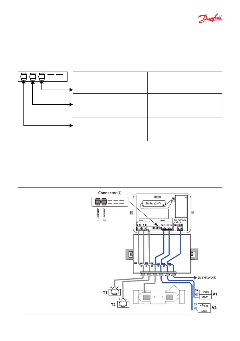
2. Electrical wiring
Wiring diagram 1
Jumper settings:
1: Additional pulse input V2 is on.
2: Additional pulse input V1 is on.
T1: flow temperature sensor.
T2: return temperature sensor.
V1: additional pulse input/output 1.
V2: additional pulse input/output 2.