8 | © Danfoss | Energy Meters | 2020.11 BC200586470576en-020601
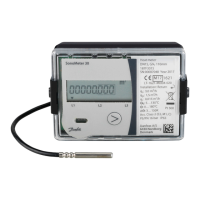
Installation guide SonoMeter 30
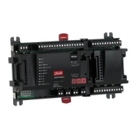
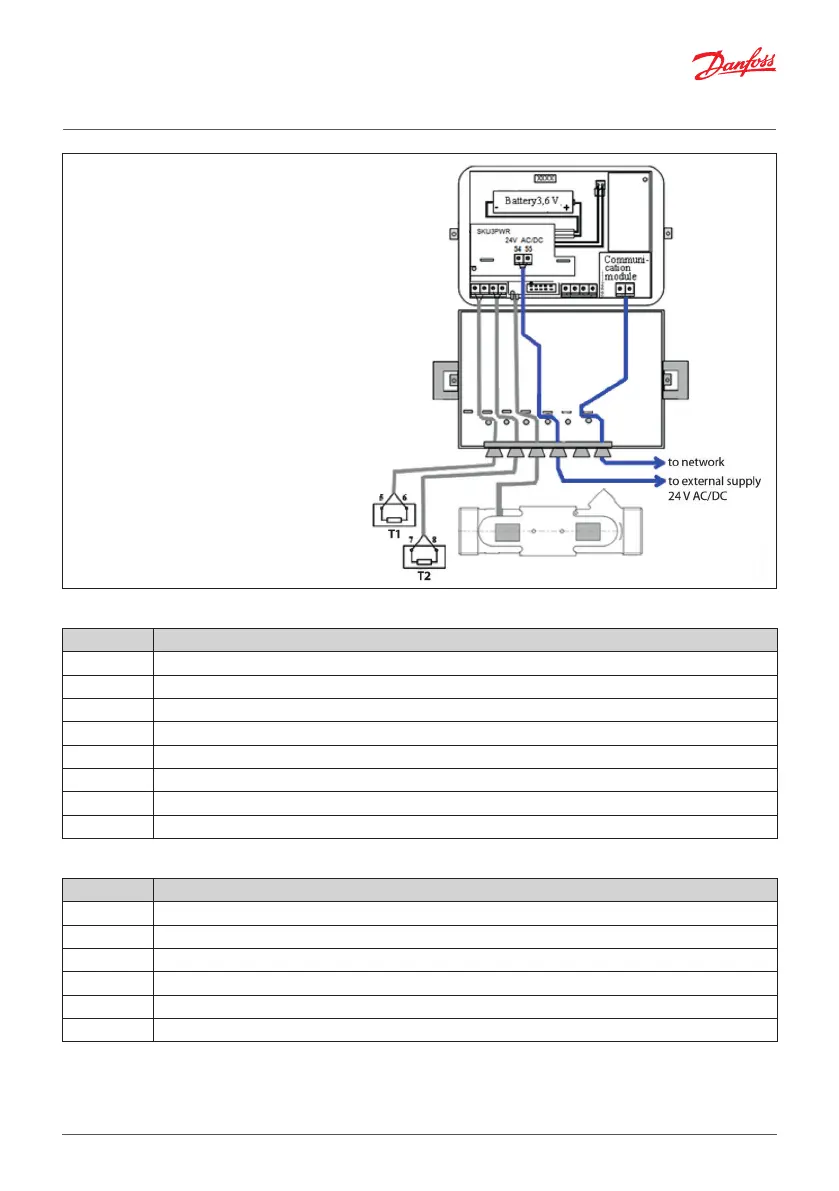
Wiring diagram 2
Connecting the meter to the mains
power supply, 24 V AC/DC.
230 V AC to 24 V AC transformer
must be used for connection to
230 V AC!
Calculator
Terminals Description
5 T1 supply temperature sensor
6 T1 supply temperature sensor
7 T2 return temperature sensor
8 T2 return temperature sensor
50 V2 additional pulse input/output GND
51 V2 additional pulse input/output (Volume output in TEST mode)
52 V1 additional pulse input/output GND
53 V1 additional pulse input/output (Energy output in TEST mode)
Communication modules
Terminals Description
24, 25 M-bus module (bipolar)
60, 61 12-24 V DC power supply voltage for Modbus and LON (bipolar)
90 RS-485 Modbus RTU module (+) or BACnet (+)
91 RS-485 Modbus RTU module (+) or BACnet (+)
96 LON module (line A)
97 LON module (line B)