VLT
®
8000 AQUA
Programming
533 Display text 1
(DISPLAY TEXT ARRAY 1)
Value:
Max. 20 characters
[XXXXXXXXXXXXXXXXXXXX]
Function:
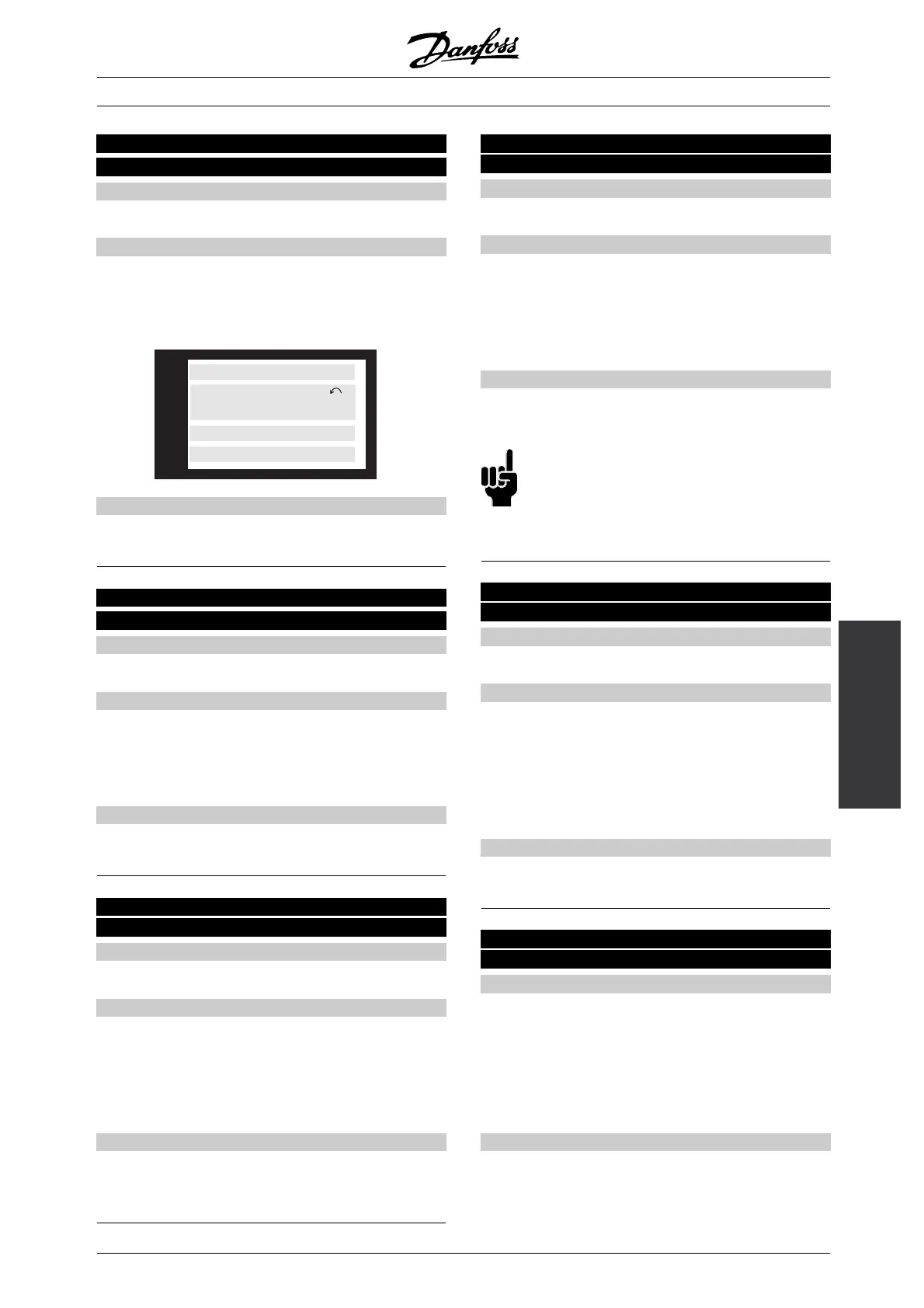
Here, a text of max. 20 characters can be written that
will be shown in display line 1, provided LCP display
text [27] has been selected in parameter 007 Large
display read-out. Example of display text.
175ZA792.10
VLT NO.8
SETUP
1
CLEANING SYSTEM NO.2
AUTO REMOTE RUNNING
Description of choice:
Write the required text via serial communication.
534 Display text 2
(DISPLAY TEXT ARRAY 2)
Value:
Max. 8 characters
[XXXXXXXX]
Function:
Here, a text of max. 8 characters can be written
that will be shown in display line 2, providedLCP
display text [27] has been selected in parameter
007 Large display read-out.
Description of choice:
Write the required text via serial communication.
535 Bus feedback 1 Bus feedback 1
(BUS FEEDBACK1)
Value:
0 - 16384 decimal (0 - 4000 Hex)
✭ 0
Function:
Via the serial communication port, this parameter
allows writing of a bus feedback value which will then
form part of the feedback handling (see Feedback
handling). Bus feedback 1 will be added to any
feedback value registered on terminal 53.
Description of choice:
Write the required bus feedback value via
serial communication.
536 Bus feedback 2
(BUS FEEDBACK2)
Value:
0 - 16384 decimal (0 - 4000 Hex)
✭ 0
Function:
Via serial communication, a bus feedback value could
be written in this parameter that would subsequently
become part of the feedback handling system (see
Feedback handling). Bus feedback 2 will be added
to any feedback value on terminal 54.
Description of choice:
Write the required bus feedback value via the
serial communication.
NB!:
Parameters 555 Bus time interval and 556
Bus time interval function are only active
when FC protocol [0] has been selected
in parameter 500 Protocol.
555 Bus time interval
(BUS TIME INTERVAL)
Value:
1 - 65534 sec.
✭ 60 sec.
Function:
In this parameter, the time is set which is expected
to pass as a maximum between the receipt of two
telegrams in a row. If this time is exceeded, the
serial communication is assumed to have stopped
and the required reaction is set in parameter
556 Bus time interval function.
Description of choice:
Set the required time.
556 Bus time interval function
(BUS TIME INTERVAL FUNCTION)
Value:
✭Off (OFF)
[0]
Freeze output (FREEZE OUTPUT)
[1]
Stop (STOP)
[2]
Jogging (JOG FREQUENCY)
[3]
Max. output frequency (MAX FREQUENCY)
[4]
Stop and trip (STOP AND TRIP)
[5]
Function:
In this parameter, the required reaction from the
frequency converter is selected when the time set in
parameter 555 Bus time interval has been exceeded.
✭
= factory setting. () = display text [] = value for use in communication via serial communication port
MG.83.A2.02 - VLT is a registered Danfoss trademark
165
 Loading...


