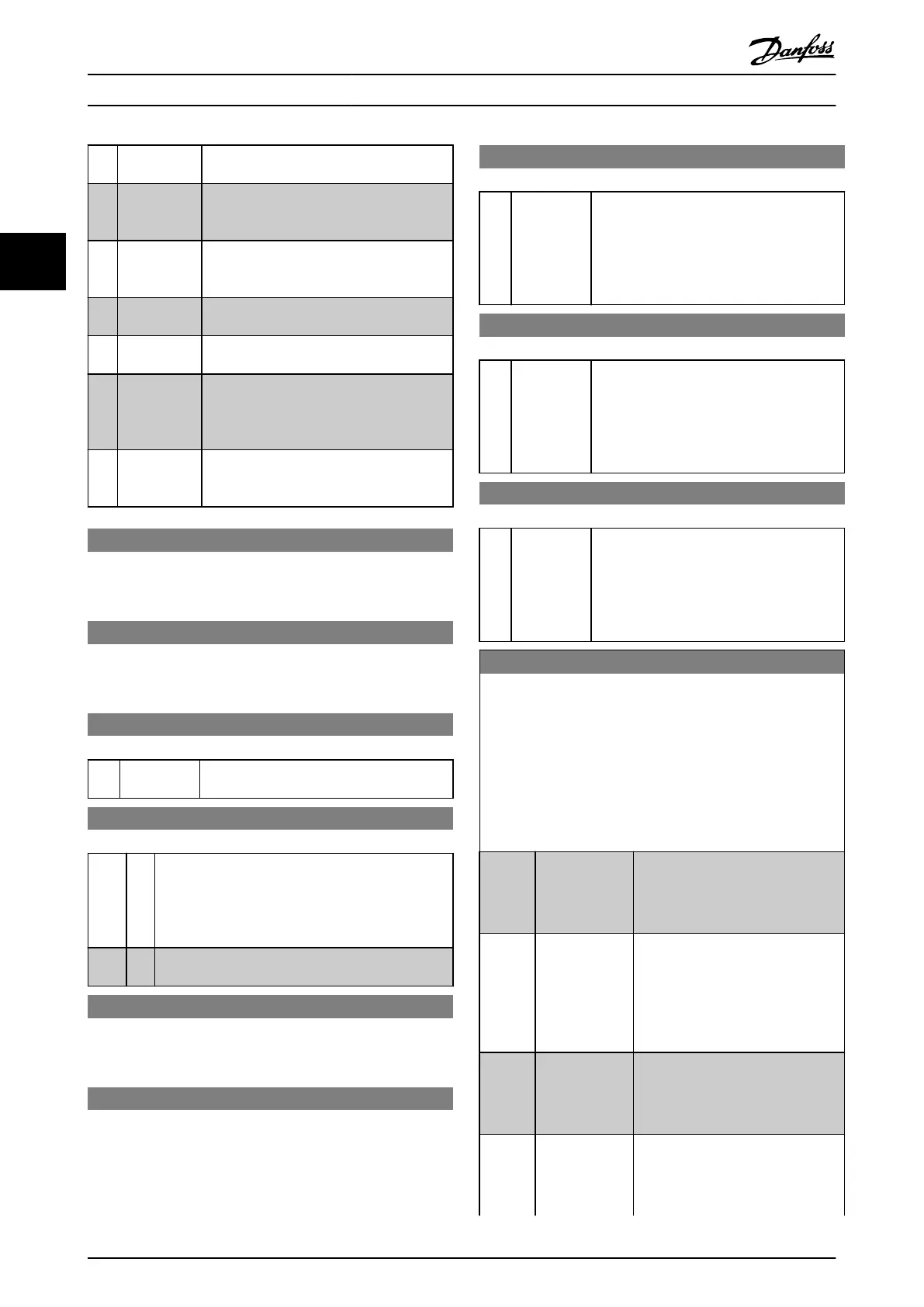
[65] Reset
Counter B
Input for reset of counter B.
[66] Sleep Mode Forces frequency converter into Sleep mode
(see parameter group 22-4*). Reacts on the
rising edge of signal applied.
[68] Timed
Actions
Disabled
Timed actions are disabled. See parameter
group 23-0* Timed Actions.
[69] Constant OFF
Timed Actions are set for Constant OFF. See
parameter group 23-0* Timed Actions.
[70] Constant ON
Timed Actions are set for Constant ON. See
parameter group 23-0* Timed Actions.
[78] Reset
Preventive
Maintenance
Word
Resets all data in
parameter 16-96 Maintenance Word to 0.
[80] PTC Card 1
ALl digital inputs can be set to [80] PTC Card
1. However, only 1 digital input must be set
to this option.
5-10 Terminal 18 Digital Input
The parameter contains all options and functions listed in
parameter group 5-1* Digital Inputs except for option [32] Pulse
input.
5-11 Terminal 19 Digital Input
The parameter contains all options and functions listed in
parameter group 5-1* Digital Inputs except for option [32] Pulse
input.
5-12 Terminal 27 Digital Input
Option: Function:
[2] * Coast inverse Functions are described under parameter
group 5-1* Digital Inputs.
5-13 Terminal 29 Digital Input
Option: Function:
Select the function from the available digital input
range and the additional options [60] Counter A (up),
[61] Counter A (down), [63] Counter B (up) and [64]
Counter B (down). Counters are used in smart logic
control functions.
[14] * Jog
Functions are described under parameter group 5-1*
Digital Inputs
5-14 Terminal 32 Digital Input
The parameter contains all options and functions listed in
parameter group 5-1* Digital Inputs except for option [32] Pulse
input.
5-15 Terminal 33 Digital Input
The parameter contains all options and functions listed in
parameter group 5-1* Digital Inputs.
5-16 Terminal X30/2 Digital Input
Option: Function:
[0] * No operation This parameter is active when option module
MCB 101 is installed in the frequency
converter. The parameter contains all options
and functions listed in parameter group 5-1*
Digital Inputs except for option [32] Pulse
input.
5-17 Terminal X30/3 Digital Input
Option: Function:
[0] * No operation This parameter is active when option module
MCB 101 is installed in the frequency
converter. The parameter contains all options
and functions listed in parameter group 5-1*
Digital Inputs except for option [32] Pulse
input.
5-18 Terminal X30/4 Digital Input
Option: Function:
[0] * No operation This parameter is active when option module
MCB 101 is installed in the frequency
converter. The parameter contains all options
and functions listed in parameter group 5-1*
Digital Inputs except for option [32] Pulse
input.
5-19 Terminal 37 Safe Stop
Use this parameter to congure the Safe Torque O functionality.
A warning message makes the frequency converter coast the
motor and enables the automatic restart. An alarm message
makes the frequency converter coast the motor and requires a
manual restart (via a eldbus, Digital I/O, or by pressing [RESET]
on the LCP). When the VLT
®
PTC Thermistor Card MCB 112 is
mounted, congure the PTC options to get the full benet from
the alarm handling.
Option: Function:
[1] Safe Stop Alarm Coasts frequency converter when
Safe Torque O is activated. Manual
reset from LCP, digital input, or
eldbus.
[3] Safe Stop
Warning
Coasts the frequency converter when
Safe Torque O is activated (terminal
37 o). When the safe-stop circuit is
re-established, the frequency
converter continues without manual
reset.
[4] PTC 1 Alarm Coasts frequency converter when
Safe Torque O is activated. Manual
reset from LCP, digital input, or
eldbus.
[5] PTC 1 Warning Coasts frequency converter when
Safe Torque O is activated (terminal
37 o). When Safe Torque O circuit
is re-established, the frequency
Parameter Descriptions
VLT
®
HVAC Drive FC 102
72 Danfoss A/S © 03/2015 All rights reserved. MG11CE02
33
 Loading...


