5-40 Function Relay
Array [8]
(Relay 1 [0], Relay 2 [1]
Option MCB 105: Relay 7 [6], Relay 8 [7] and Relay 9 [8]).
Select options to dene the function of the relays.
The selection of each mechanical relay is realised in an array
parameter.
Option: Function:
[71] Logic rule 1
[72] Logic rule 2
[73] Logic rule 3
[74] Logic rule 4
[75] Logic rule 5
[80] SL digital output A
[81] SL digital output B
[82] SL digital output C
[83] SL digital output D
[84] SL digital output E
[85] SL digital output F
[160] No alarm
[161] Running reverse
[165] Local ref active
[166] Remote ref active
[167] Start command activ
[168] Hand / O
[169] Auto mode
[180] Clock Fault
[181] Prev. Maintenance
[188] AHF Capacitor Connect
[189] External Fan Control
[190] No-Flow
[191] Dry Pump
[192] End Of Curve
[193] Sleep Mode
[194] Broken Belt
[195] Bypass Valve Control
[196] Fire Mode
[197] Fire Mode was Act.
[198] Drive Bypass
[211] Cascade Pump 1
[212] Cascade Pump 2
[213] Cascade Pump 3
5-41 On Delay, Relay
Array [2], (Relay 1 [0], Relay 2 [1])
Range: Function:
0.01 s* [0.01 - 600 s] Enter the delay of the relay cut-in time.
Select 1 of 2 internal mechanical relays in
an array function. See 5-40 Function Relay
for details.
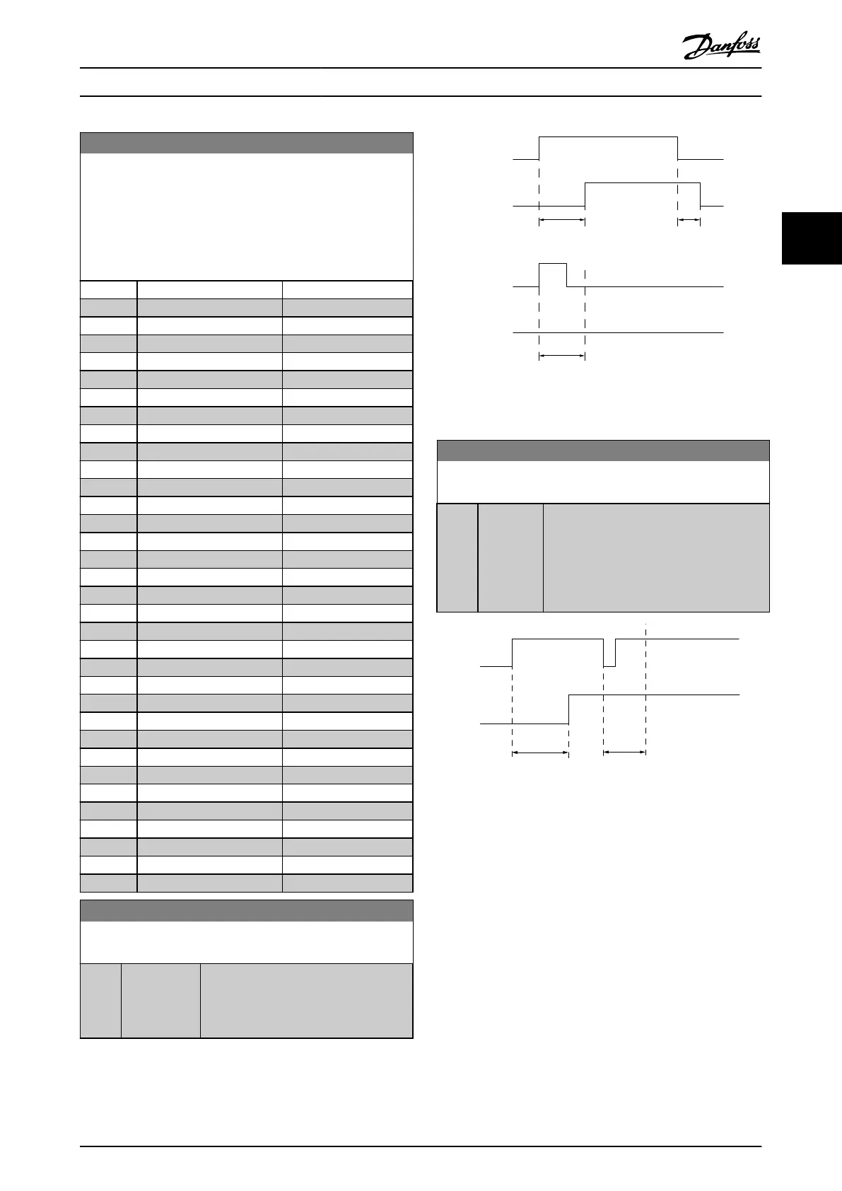
Selected
Event
Relay
output
Selected
Event
Relay
output
On Delay
P 5-41
On Delay
P 5-41
O Delay
P 5-42
130BA171.10
Illustration 3.25 On Delay, Relay
5-42
O Delay, Relay
Array[2]: Relay1[0], Relay2[1]
Range: Function:
0.01 s* [0.01 -
600 s]
Enter the delay of the relay cut out time.
Select 1 of 2 internal mechanical relays in
an array function. See 5-40 Function Relay
for details. If the selected event condition
changes before a delay timer expires, the
relay output is unaected.
Selected
Event
Relay
output
On Delay
P 5-41
O Delay
P 5-42
130BA172.10
Illustration 3.26 O Delay, Relay
If the selected event condition changes before the on
delay or o delay timer expires, the relay output is
unaected.
3.7.5
5-5* Pulse Input
The pulse input parameters are used to dene an
appropriate window for the impulse reference area by
conguring the scaling and lter settings for the pulse
inputs. Input terminal 29 or 33 acts as frequency reference
inputs. Set terminal 29 (parameter 5-13 Terminal 29 Digital
Input) or terminal 33 (5-15 Terminal 33 Digital Input) to [32]
Pulse input. If terminal 29 is used as an input, set
parameter 5-02 Terminal 29 Mode to [0] Input.
Parameter Descriptions
Programming Guide
MG11CE02 Danfoss A/S © 03/2015 All rights reserved. 77
3 3
 Loading...


