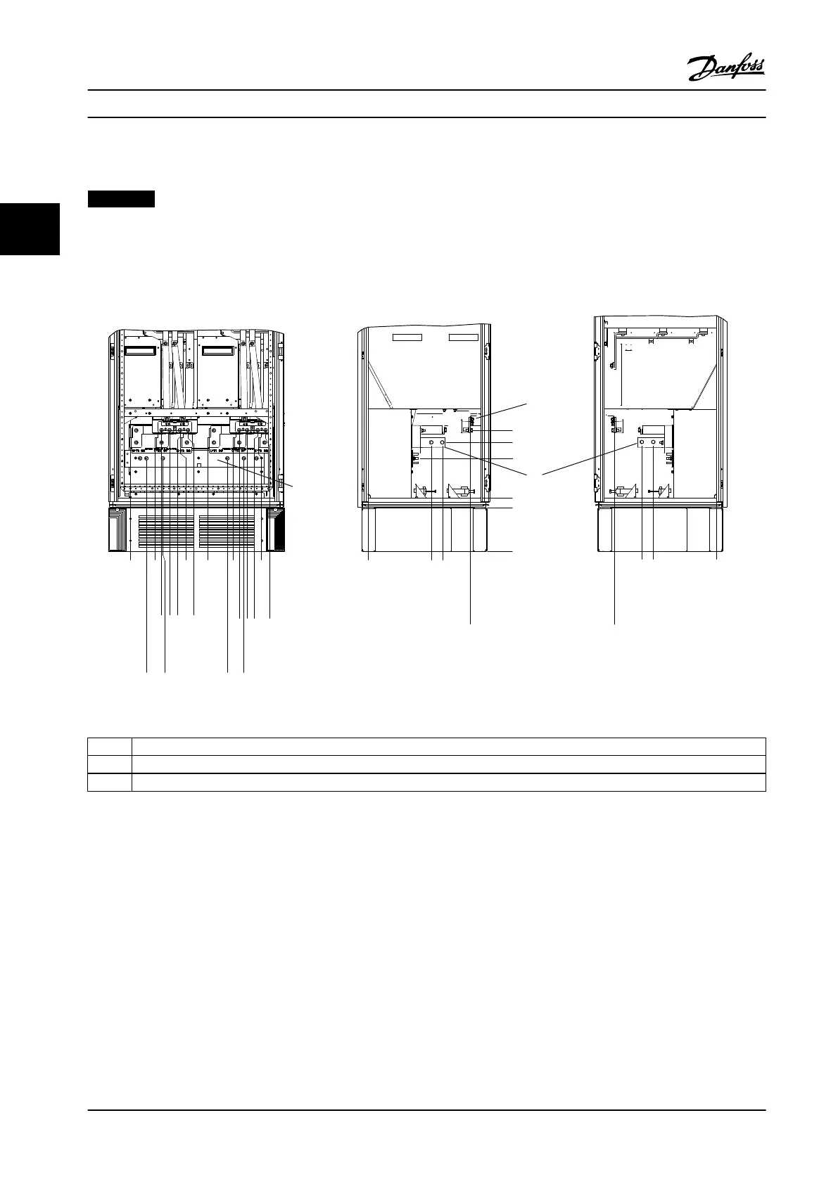
3.3.4 Terminal Locations - Enclosure type F
NOTICE!
The F enclosures are available in four dierent sizes, F1, F2, F3 and F4. The F1 and F2 consist of an inverter cabinet on
the right and rectier cabinet on the left. The F3 and F4 have an extra options cabinet left of the rectier cabinet. The
F3 is an F1 with an extra options cabinet. The F4 is an F2 with an extra options cabinet.
Terminal locations - enclosure types F1 and F3
.0 [.0]
54.4[2.1]
169.4 [6.7]
284.4 [11.2]
407.3 [16.0]
522.3 [20.6]
637.3 [25.1]
287.4 [11.3]
253.1 [10.0]
.0 [.0]
.0 [.0]
339.4 [13.4]
287.4 [11.3]
.0 [.0]
339.4 [13.4]
308.3 [12.1]
465.6 [18.3]
465.6 [18.3]
198.1[7.8]
234.1 [9.2]
282.1 [11.1]
318.1 [12.5]
551.0 [21.7]
587.0 [23.1]
635.0 [25.0]
671.0 [26.4]
44.40 [1.75]
244.40 [9.62]
1 Ground bar
2 Motor terminals
3 Brake terminals
Figure 3.24 Terminal Locations - Inverter Cabinet - F1 and F3 (Front, Left and Right Side View). The Connector Plate is 42 mm (1.65
in) below .0 level.
Mechanical Installation
VLT
®
HVAC Drive FC 102
24 Danfoss A/S © 08/2014 All rights reserved. MG11F522
33
 Loading...


