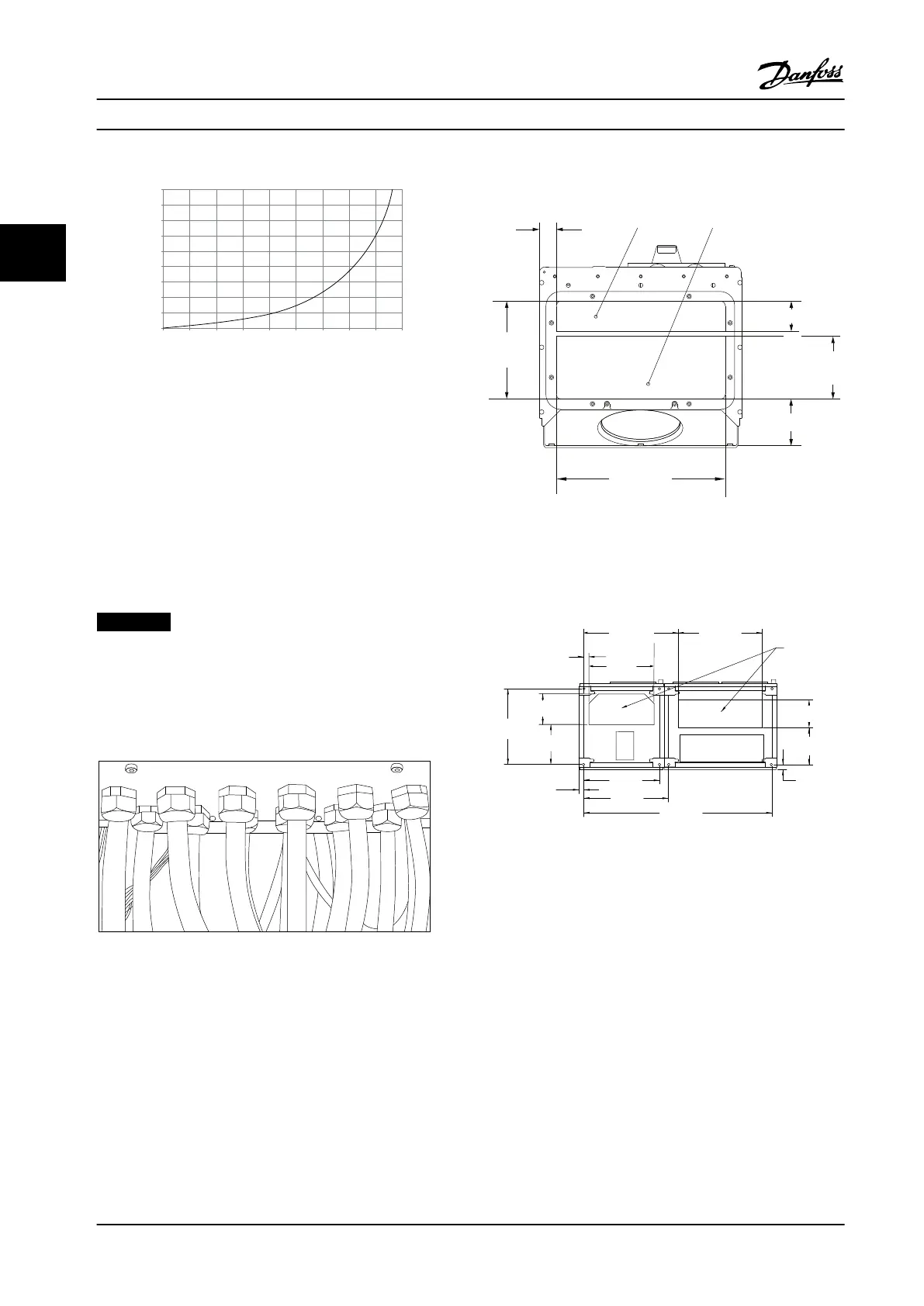
90
80
70
60
50
40
30
20
10
0
(%)
Drive Derating
0 25 50 75 100 125 150 175 225
130BB190.10
200
Pressure Change
Figure 3.33 F1, F2, F3, F4 Enclosures Derating vs. Pressure
Change
Adjustable Frequency Drive
Airow: 580 cfm (985 m
3
/h)
3.3.6
Gland/Conduit Entry - IP21 (NEMA 1)
and IP54 (NEMA12)
Cables are connected through the gland plate from the
bottom. Remove the plate and plan where to place the
entry for the glands or conduits. Prepare holes in the
marked area in Figure 3.35 to Figure 3.39.
NOTICE!
The gland plate must be tted to the frequency
converter to ensure the specied protection degree, as
well as ensuring proper cooling of the unit. If the gland
plate is not mounted, the frequency converter may trip
on Alarm 69, Pwr. Card Temp
Figure 3.34 Example of Proper Installation of Gland Plate
Cable entries viewed from the bottom of the frequency
converter - 1) Mains side 2) Motor side
2
1
176FA289.12
35
350
202.8
98.6
130.0
62.5
Figure 3.35 Enclosure Size E1
Enclosure sizes F1-F4: Cable entries viewed from the
bottom of the frequency converter - 1) Place conduits in
marked areas
1
130BA837.12
1328.8
(52.315)
595.8
(23.457)
533.0
(20.984)
36.2
(1.425)
281.8
(11.096)
535.0
(21.063)
216.5
(8.524)
37.7
(1.485)
460.0
(18.110)
668.3
(26.311)
593.0
(23.346)
199.5
(7.854)
258.5
(10.177)
35.5
(1.398)
Figure 3.36 Enclosure Size F1
Mechanical Installation
VLT
®
HVAC Drive FC 102
30 Danfoss A/S © 08/2014 All rights reserved. MG11F522
33
 Loading...


