CAUTION
Install a door fan on the enclosure to remove the heat
losses not contained in the backchannel of the
adjustable frequency drive and any additional losses
generated from other components installed inside the
enclosure. Calculate the total required airow to select
the appropriate fans. Some enclosure manufacturers
oer software for performing the calculations (Rittal
Therm software). If the adjustable frequency drive is the
only heat-generating component in the enclosure, the
minimum airow required at an ambient temperature of
45 °C (113 °F) for the E2 adjustable frequency drive is
782 m
3
/h (460 cfm).
Airow
Provide sucient airow over the heatsink. The ow rate is
shown in Table 3.8.
Enclosure
protection
rating
Enclosure size
Door fan/
top fan
airow
Heatsink fan
IP21/NEMA 1
IP54/NEMA 12
E1 P315T4,
P450T7,
P500T7
340 m
3
/h
(200 cfm)
1105 m
3
/h
(650 cfm)
E1 P355-
P450T4, P560-
P630T7
340 m
3
/h
(200 cfm)
1445 m
3
/h
(850 cfm)
IP21/NEMA 1 F1, F2, F3 and
F4
700 m
3
/h
(412 cfm)*
985 m
3
/h
(580 cfm)*
IP54/NEMA 12 F1, F2, F3 and
F4
525 m
3
/h
(309 cfm)*
985 m
3
/h
(580 cfm)*
IP00/Chassis
E2 P315T4,
P450T7,
P500T7
255 m
3
/h
(150 cfm)
1105 m
3
/h
(650 cfm)
E2 P355-
P450T4, P560-
P630T7
255 m
3
/h
(150 cfm)
1445 m
3
/h
(850 cfm)
* Airow per fan. Enclosure type F contains multiple fans.
Table 3.8 Heatsink Airow
NOTICE!
The fan runs for the following reasons:
•
AMA.
•
DC Hold.
•
Pre-Mag.
•
DC Brake.
•
60% of nominal current is exceeded.
•
Specic heatsink temperature is exceeded
(power-size dependent).
•
Specic power card ambient temperature is
exceeded (power-size dependent).
•
Specic control card ambient temperature is
exceeded.
Once the fan is started, it runs for minimum 10 minutes.
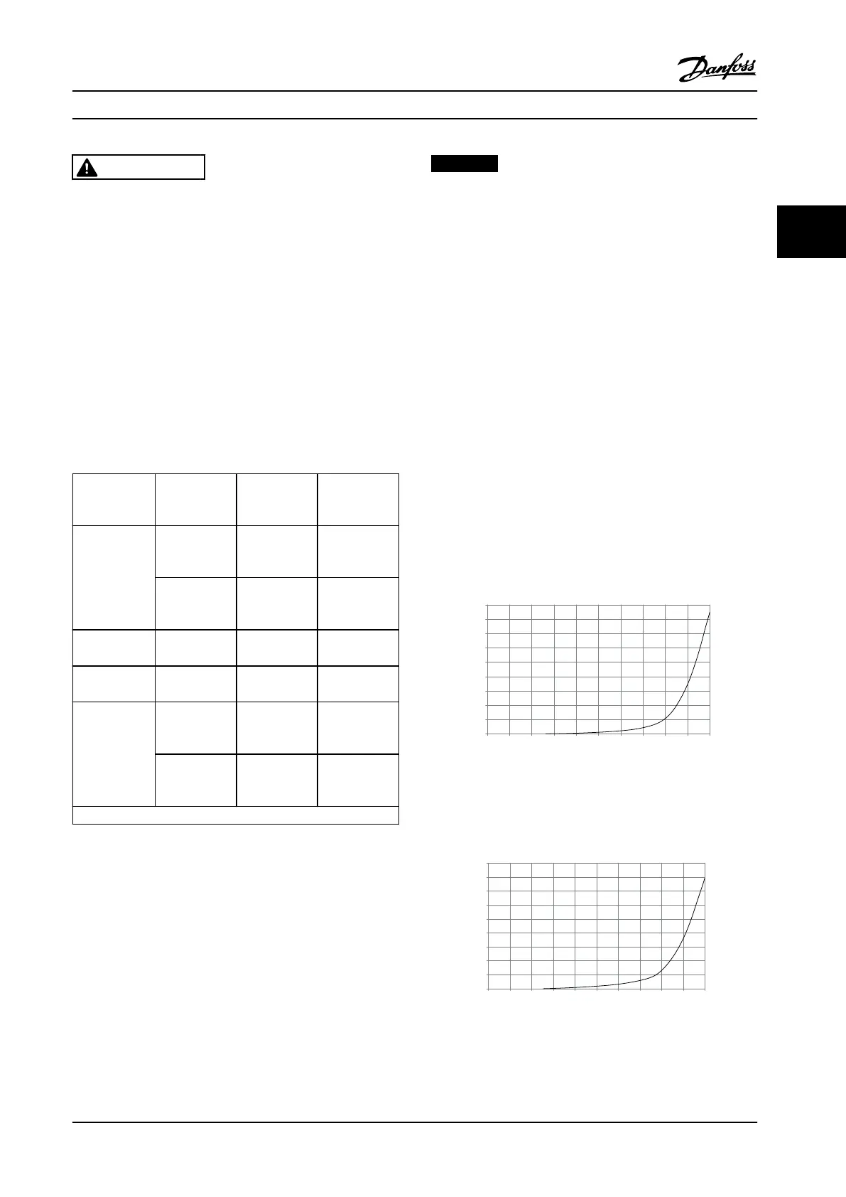
External ducts
If extra duct work is added externally to the Rittal cabinet,
calculate the pressure drop in the ducting. Use the
following charts to derate the adjustable frequency drive
according to the pressure drop.
90
80
70
60
50
40
30
20
10
0
(%)
Drive Derating
0 0 0.1 3.6 9.8 21.5 43.4 76 237.5 278.9
(Pa)
Pressure Change
130BB010.10
147.1
Figure 3.31 E Enclosure Derating vs. Pressure Change (Small
Fan), P315T4 and P450T7-P500T7
Adjustable Frequency Drive Airow: 650 cfm (1105 m
3
/h)
90
80
70
60
50
40
30
20
10
0
(%)
Drive Derating
0 0.2 0.6 2.2 5.8 11.4 18.1 30.8 152.8 210.8
(Pa)
Pressure Change
130BB011.10
69.5
Figure 3.32 E Enclosure Derating vs. Pressure Change (Large
Fan), P355T4-P450T4 and P560T7-P630T7
Adjustable Frequency Drive Airow: 850 cfm (1445 m
3
/h)
Mechanical Installation Instruction Manual
MG11F522 Danfoss A/S © 08/2014 All rights reserved. 29
3 3
 Loading...


