22-80 Flow Compensation
Option: Function:
[0] Disabled Set-Point compensation not active.
[1] Enabled Set-Point compensation is active. Enabling this
parameter allows the Flow Compensated Setpoint
operation.
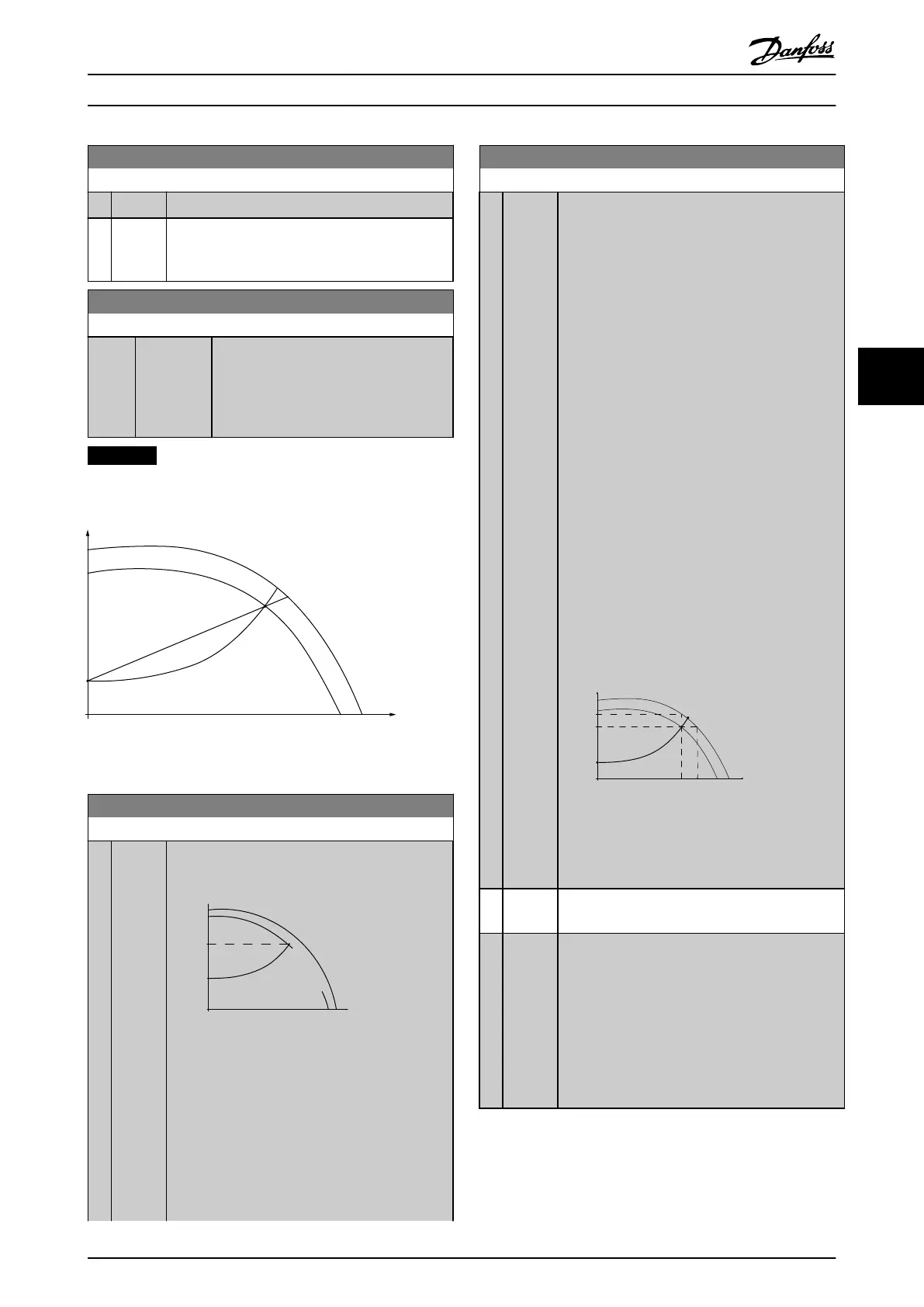
22-81 Square-linear Curve Approximation
Range: Function:
100 %* [0 - 100 %]
Example 1:
Adjustment of this parameter allows the
shape of the control curve to be adjusted.
0 = Linear
100% = Ideal shape (theoretical).
NOTICE
Not visible when running in cascade.
Control Curve
(head)
(ow)
H
Q
130BA388.11
100%
P22-81 0%
Illustration 5.23
22-82 Work Point Calculation
Option: Function:
Example 1:
A
130BA385.11
P22-85/22-86
Control Curve
H
MIN
H
DESIGN
Set Point
n
RATED
_
f
RATED
n
DESIGN
-
f
DESIGN
Q
(flow)
H
(head)
Par.:
22-83/
22-84/
22-87
Illustration 5.24 Speed at System Design
Working Point is Known
From the data sheet showing characteristics for the
specific equipment at different speeds, simply
reading across from the H
DESIGN
point and the
Q
DESIGN
point allows us to find point A, which is the
System Design Working Point. The pump character-
22-82 Work Point Calculation
Option: Function:
istics at this point should be identified and the
associated speed programmed. Closing the valves
and adjusting the speed until H
MIN
has been
achieved allows the speed at the no flow point to
be identified.
Adjustment of parameter 22-81 Square-linear Curve
Approximation then allows the shape of the control
curve to be adjusted infinitely.
Example 2:
Speed at System Design Working Point is not
known: Where the Speed at System Design
Working Point is unknown, another reference point
on the control curve needs to be determined by
means of the data sheet. By looking at the curve
for the rated speed and plotting the design
pressure (H
DESIGN
, Point C) the flow at that pressure
Q
RATED
can be determined. Similarly, by plotting the
design flow (Q
DESIGN
, Point D). The pressure H
DESIGN
at that flow can be determined. Knowing these
two points on the pump curve, along with H
MIN
as
described above, allows the frequency converter to
calculate the reference point B and thus to plot the
control curve which will also include the System
design Working Point A.
Set point
Control Curve
n
D
E
S
I
G
N
-
f
D
E
S
I
G
N
n
R
A
T
E
D
-
f
R
A
T
E
D
(head)H
H
RATED
Par.
22-88
Q
DESIGN
Par.
22-89
H
MIN
D
B
C
A
Q
RATED
Par.
22-90
(flow)
Q
H
DESIGN
130BA387.11
22-84/
22-87
22-83/
Par.:
Illustration 5.25
[0] Disabled Work Point Calculation not active. To be used if
speed at design point is known.
[1] Enabled Work Point Calculation is active. Enabling this
parameter allows the calculation of the unknown
System Design Working Point at 50/60 Hz speed,
from the input data set in parameter 22-83 Speed at
No-Flow [RPM] parameter 22-84 Speed at No-Flow
[Hz], parameter 22-87 Pressure at No-Flow Speed,
parameter 22-88 Pressure at Rated Speed, 22-89 Flow
at Design Point and parameter 22-90 Flow at Rated
Speed.
How to programme the freque... VLT AQUA Drive FC 202 Operation Instructions
MG20P402 - Rev. 2013-12-16 107
5 5

 Loading...


