Display lines 2 and 3 in the LCP show the status for Timed
Actions Mode (0-23 Display Line 2 Large and 0-24 Display
Line 3 Large, setting [1643] Timed Actions Status).
NOTICE
A change in mode via the digital inputs can only take
place if 23-08 Timed Actions Mode is set for [0] Times
Actions Auto.
If commands are applied simultaneously to the digital
inputs for Constant OFF and Constant ON, the Timed
Actions mode will change to Timed Actions Auto and the
two commands will be disregarded.
If 0-70 Date and Time is not set or the frequency
converter is set to HAND or OFF mode (e.g. via the LCP),
the Timed Actions mode will be change to Timed Actions
Disabled.
The Timed Actions have a higher priority than the same
actions/commands activated by the digital inputs or the
Smart Logic Controller.
The actions programmed in Timed Actions are merged
with corresponding actions from digital inputs, control
word via bus and Smart Logic Controller, according to
merge rules set up in parameter group 8-5* Digital/Bus.
NOTICE
The clock (parameter group 0-7*) must be correctly
programmed for Timed Actions to function correctly.
NOTICE
When mounting an Analog I/O MCB 109 option card, a
battery back up of the date and time is included.
NOTICE
The PC-based Configuration Tool MCT 10 Set-up
Software comprises a special guide for easy
programming of Timed Actions.
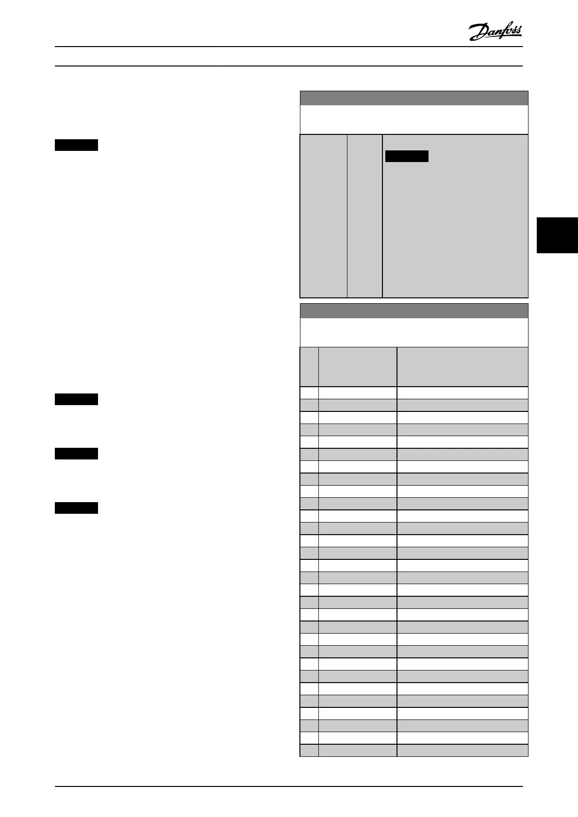
23-00 ON Time
Array [10]
Range: Function:
Size related* [ 0 - 0 ] Sets the ON time for the Timed Action.
NOTICE
The frequency converter has no
back up of the clock function and
the set date/time will reset to
default (2000-01-01 00:00) after a
power down unless a Real Time
Clock module with back up is
installed. In 0-79 Clock Fault it is
possible to program for a Warning
in case clock has not been set
properly, e.g. after a power down.
23-01 ON Action
Arra [10]
Option: Function:
Select the action during ON Time.
See 13-52 SL Controller Action for
descriptions of the options.
[0] Disabled
[1] No action
[2] Select set-up 1
[3] Select set-up 2
[4] Select set-up 3
[5] Select set-up 4
[10] Select preset ref 0
[11] Select preset ref 1
[12] Select preset ref 2
[13] Select preset ref 3
[14] Select preset ref 4
[15] Select preset ref 5
[16] Select preset ref 6
[17] Select preset ref 7
[18] Select ramp 1
[19] Select ramp 2
[22] Run
[23] Run reverse
[24] Stop
[26] DC Brake
[27] Coast
[28] Freeze output
[29] Start timer 0
[30] Start timer 1
[31] Start timer 2
[32] Set digital out A low
[33] Set digital out B low
[34] Set digital out C low
[35] Set digital out D low
[36] Set digital out E low
How to programme the freque... VLT AQUA Drive FC 202 Operation Instructions
MG20P402 - Rev. 2013-12-16 109
5 5

 Loading...


