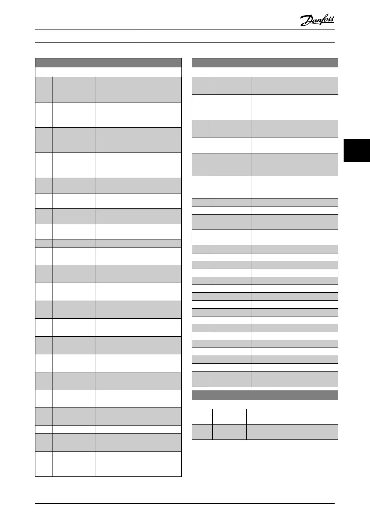
0-20 Display Line 1.1 Small
Option: Function:
[1832] Analog Input
X42/5
Shows the value of the signal applied
to terminal X42/5 on the Analog I/O
card.
[1833] Analog Out X42/7
[V]
Shows the value of the signal applied
to terminal X42/7 on the Analog I/O
card.
[1834] Analog Out X42/9
[V]
Shows the value of the signal applied
to terminal X42/9 on the Analog I/O
card.
[1835] Analog Out
X42/11 [V]
Shows the value of the signal applied
to terminal X42/11 on the Analog I/O
card.
[1836] Analog Input
X48/2 [mA]
[1837] Temp. Input
X48/4
[1838] Temp. Input
X48/7
[1839] Temp. Input
X48/10
[1860] Digital Input 2
[2117] Ext. 1 Reference
[Unit]
The value of the reference for
extended Closed Loop Controller 1
[2118] Ext. 1 Feedback
[Unit]
The value of the feedback signal for
extended Closed Loop Controller 1
[2119] Ext. 1 Output [%] The value of the output from
extended Closed Loop Controller 1
[2137] Ext. 2 Reference
[Unit]
The value of the reference for
extended Closed Loop Controller 2
[2138] Ext. 2 Feedback
[Unit]
The value of the feedback signal for
extended Closed Loop Controller 2
[2139] Ext. 2 Output [%] The value of the output from
extended Closed Loop Controller 2
[2157] Ext. 3 Reference
[Unit]
The value of the reference for
extended Closed Loop Controller 3
[2158] Ext. 3 Feedback
[Unit]
The value of the feedback signal for
extended Closed Loop Controller 3
[2159] Ext. 3 Output [%] The value of the output from
extended Closed Loop Controller 3
[2230] No-Flow Power The calculated No Flow Power for the
actual operating speed
[2316] Maintenance Text
[2580] Cascade Status Status for the operation of the
Cascade Controller
[2581] Pump Status Status for the operation of each
individual pump controlled by the
Cascade Controller
0-20 Display Line 1.1 Small
Option: Function:
[2791] Cascade
Reference
Reference output for use with
follower drives.
[2792] % Of Total
Capacity
Readout parameter to show the
system operating point as a %
capacity of total system capacity.
[2793] Cascade Option
Status
Readout parameter to show the status
of the cascade system.
[2794] Cascade System
Status
[2795] Advanced
Cascade Relay
Output [bin]
[2796] Extended Cascade
Relay Output
[bin]
[2920] Derag Power[kW]
[2921] Derag Power[HP]
[3110] Bypass Status
Word
[3111] Bypass Running
Hours
[9920] HS Temp. (PC1)
[9921] HS Temp. (PC2)
[9922] HS Temp. (PC3)
[9923] HS Temp. (PC4)
[9924] HS Temp. (PC5)
[9925] HS Temp. (PC6)
[9926] HS Temp. (PC7)
[9927] HS Temp. (PC8)
[9951] PC Debug 0
[9952] PC Debug 1
[9953] PC Debug 2
[9954] PC Debug 3
[9955] PC Debug 4
[9956] Fan 1 Feedback
[9957] Fan 2 Feedback
[9958] PC Auxiliary Temp
[9959] Power Card
Temp.
0-21 Display Line 1.2 Small
Option: Function:
Select a variable for display in line 1,
middle position.
[1662] * Analog input
53
The options are the same as those listed
for par. 0-20 Display Line 1.1 Small.
How to programme the freque... VLT AQUA Drive FC 202 Operation Instructions
MG20P402 - Rev. 2013-12-16 87
5 5

 Loading...


