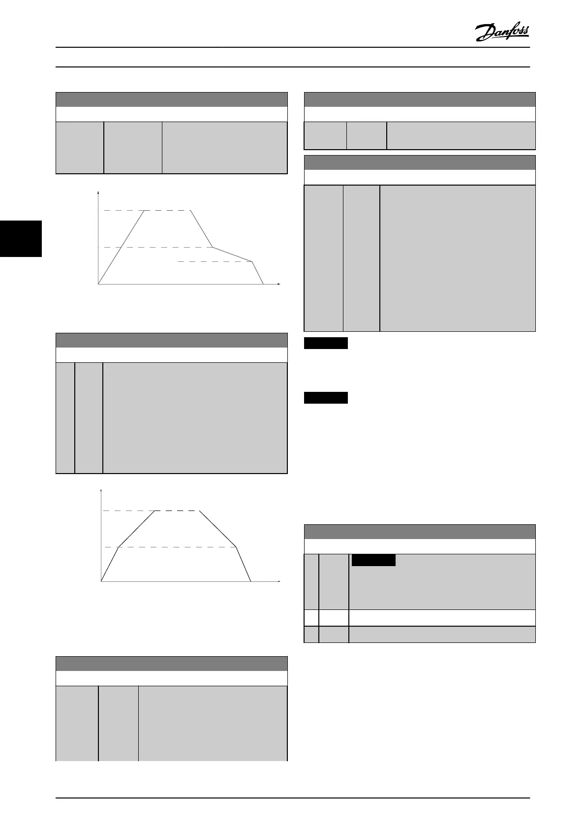
3-87 Check Valve Ramp End Speed [HZ]
Range: Function:
Size related* [ 0 - par. 4-12
Hz]
Set the speed in [Hz] below Motor
Speed Low Limit where the Check
Valve Ramp should no longer be
active.
130BA961.10
Speed
Motor Speed
Normal
Check valve
Motor Speed
High
Low
Time
Ramp
End Speed
Illustration 5.16
3-88 Final Ramp Time
Range: Function:
0 s* [0 -
60 s]
Enter the Final Ramp Time to be used when
ramping down from Motor Speed Low Limit,
parameter 4-11 Motor Speed Low Limit [RPM] or
4-12 Motor Speed Low Limit [Hz], to zero speed.
Submersible deep well pumps can be damaged by
running below minimum speed. A fast ramp time
below minimum pump speed is recommended. This
parameter may be applied as a fast ramp rate from
Motor Speed Low Limit to zero speed.
130BA962.10
Motor Speed
Motor Speed
High
Low
Normal
Ramps
Initial
Ramp
Final
Ramp
Time
Speed
Illustration 5.17
5.2.4 4-** Limits and Warnings
4-11 Motor Speed Low Limit [RPM]
Range: Function:
Size
related*
[ 0 - par.
4-13
RPM]
Enter the minimum limit for motor speed.
The motor speed low limit can be set to
correspond to the manufacturer’s
recommended minimum motor speed.
The motor speed low limit must not
exceed the setting in
4-11 Motor Speed Low Limit [RPM]
Range: Function:
parameter 4-13 Motor Speed High Limit
[RPM].
4-13 Motor Speed High Limit [RPM]
Range: Function:
Size
related*
[ 0 -
60000
RPM]
Enter the maximum limit for motor speed.
The motor speed high limit can be set to
correspond to the manufacturer’s maximum
rated motor. The motor speed high limit
must exceed the setting in
parameter 4-11 Motor Speed Low Limit
[RPM]. Only parameter 4-11 Motor Speed
Low Limit [RPM] or 4-12 Motor Speed Low
Limit [Hz] is displayed depending on other
parameters in the Main Menu and
depending on default settings dependant
on global location.
NOTICE
Max. output frequency cannot exceed 10% of the
inverter switching frequency (14-01 Switching Frequency).
NOTICE
Any changes in parameter 4-13 Motor Speed High Limit
[RPM] reset the value in 4-53 Warning Speed High to the
same value as set in parameter 4-13 Motor Speed High
Limit [RPM].
5.2.5 5-** Digital In/Out
Parameter group for configuring the digital input and
output.
5-01 Terminal 27 Mode
Option: Function:
NOTICE
This parameter cannot be adjusted while the
motor is running.
[0] Input Defines terminal 27 as a digital input.
[1] Output Defines terminal 27 as a digital output.
5.2.6 5-1* Digital Inputs
Parameters for configuring the input functions for the
input terminals.
The digital inputs are used for selecting various functions
in the frequency converter. All digital inputs can be set to
the following functions:
How to programme the freque...
VLT AQUA Drive FC 202 Operation Instructions
92 MG20P402 - Rev. 2013-12-16
55

 Loading...


