Functions dedicated to only one digital input are stated in
the associated parameter.
All digital inputs can be programmed to these functions:
[0] No operation No reaction to signals transmitted to
terminal.
[1] Reset Resets frequency converter after a TRIP/
ALARM. Not all alarms can be reset.
[2] Coast inverse
Leaves motor in free mode. Logic ‘0’ ⇒
coasting stop.
(Default Digital input 27): Coasting stop,
inverted input (NC).
[3] Coast and
reset inverse
Reset and coasting stop Inverted input (NC).
Leaves motor in free mode and resets the
frequency converter. Logic ‘0’ ⇒ coasting
stop and reset.
[5] DC-brake
inverse
Inverted input for DC braking (NC).
Stops motor by energizing it with a DC
current for a certain time period. See
2-01 DC Brake Current to 2-03 DC Brake Cut
In Speed [RPM]. The function is only active
when the value in 2-02 DC Braking Time is
different from 0. Logic ’0’ ⇒ DC braking.
This selection is not possible when
1-10 Motor Construction is set to [1] PM, non
salient SPM
[6] Stop inverse Stop Inverted function. Generates a stop
function when the selected terminal goes
from logical level ‘1’ to ‘0’. The stop is
performed according to the selected ramp
time (parameter 3-42 Ramp 1 Ramp Down
Time and 3-52 Ramp 2 Ramp Down Time.
NOTICE
When the frequency converter is at
the torque limit and has received a
stop command, it may not stop by
itself. To ensure that the frequency
converter stops, configure a digital
output to [27] Torque limit & stop and
connect this digital output to a digital
input that is configured as coast.
[7] External
Interlock
Same function as Coasting stop, inverse, but
External Interlock generates the alarm
message ’external fault’ on the display when
the terminal which is programmed for Coast
Inverse is logic ‘0’. The alarm message will
also be active via digital outputs and relay
outputs, if programmed for External
Interlock. The alarm can be reset using a
digital input or the [Reset] key if the cause
for the External Interlock has been removed.
A delay can be programmed in
22-00 External Interlock Delay. After applying
a signal to the input, the reaction described
above will be delayed with the time set in
22-00 External Interlock Delay.
[8] Start Select start value for a start/stop command.
‘1’ = start, ‘0 ’ = stop.
(Default Digital input 18)
[9] Latched start Motor starts, if a pulse is applied for min. 2
ms. Motor stops when Stop inverse is
activated
[10] Reversing Changes direction of motor shaft rotation.
Select Logic ‘1’ to reverse. The reversing
signal only changes the direction of
rotation. It does not activate the start
function. Select both directions in
4-10 Motor Speed Direction.
(Default Digital input 19).
[11] Start
reversing
Used for start/stop and for reversing on the
same wire. Signals on start are not allowed
at the same time.
[14] Jog
Used for activating jog speed. See 3-11 Jog
Speed [Hz].
(Default Digital input 29)
[15] Preset
reference on
Used for shifting between external reference
and preset reference. It is assumed that [1]
External/preset has been selected in
parameter 3-04 Reference Function. Logic '0'
= external reference active; logic '1' = one
of the eight preset references is active.
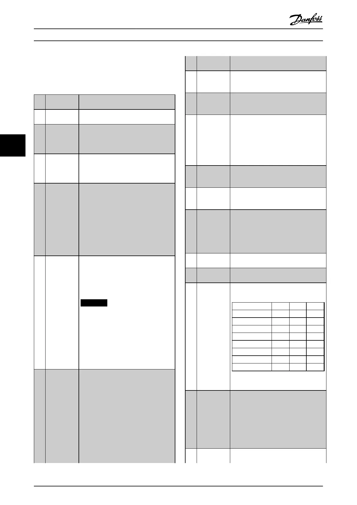
[16] Preset ref bit
0
Enables a choice between one of the eight
preset references according to Table 5.8.
[17] Preset ref bit
1
Enables a choice between one of the eight
preset references according to Table 5.8.
[18] Preset ref bit
2
Enables a choice between one of the eight
preset references according to Table 5.8.
Preset ref. bit 2 1 0
Preset ref. 0 0 0 0
Preset ref. 1 0 0 1
Preset ref. 2 0 1 0
Preset ref. 3 0 1 1
Preset ref. 4 1 0 0
Preset ref. 5 1 0 1
Preset ref. 6 1 1 0
Preset ref. 7 1 1 1
Table 5.8 Preset Ref. Bit
[19] Freeze ref Freezes actual reference. The frozen
reference is now the point of enable/
condition for Speed up and Speed down to
be used. If Speed up/down is used, the
speed change always follows ramp 2
(3-51 Ramp 2 Ramp Up Time and 3-52 Ramp
2 Ramp Down Time) in the range 0 -
3-03 Maximum Reference Maximum Reference.
[20] Freeze output Freezes actual motor frequency (Hz). The
frozen motor frequency is now the point of
How to programme the freque... VLT AQUA Drive FC 202 Operation Instructions
94 MG20P402 - Rev. 2013-12-16
55

 Loading...


