[85] Latched
Pump Derag
Starts deragging.
Options [120] - [138] are related to the Cascade Controller
functionality. For more information, see parameter group
25-** Cascade Controller.
[120] Lead Pump
Start
Starts/Stops the Lead Pump (controlled by
the frequency converter). A start requires
that also a System Start signal has been
applied e.g. to one of the digital inputs set
for [8] Start!
[121] Lead Pump
Alternation
Forces alternation of the lead pump in a
Cascade Controller. Lead Pump Alternation,
25-50 Lead Pump Alternation must be set to
either [2] At Command or [3] At Staging or
At Command. 25-51 Alternation Event can be
set to any of the four options.
[130
-
138]
Pump1
Interlock -
Pump9
Interlock
The function depends on the setting in
25-06 Number of Pumps. If set to [0] No,
then Pump1 refers to the pump controlled
by relay RELAY1 etc. If set to [1] Yes, Pump1
refers to the pump controlled by the
frequency converter only (without any of
the build in relays involved) and Pump2 to
the pump controlled by the relay RELAY1.
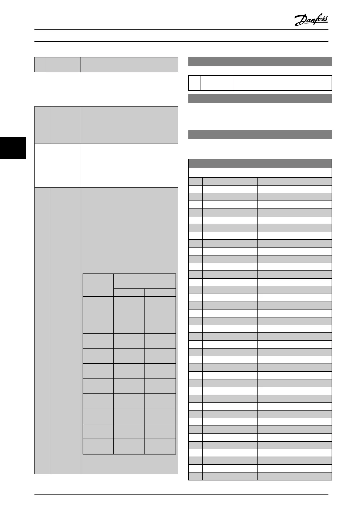
Variable speed pump (lead) cannot be
interlocked in the basic Cascade Controller.
See Table 5.9
Setting in
parameter
group 5-1*
Setting in 25-06 Number of
Pumps
[0] No [1] Yes
[130] Pump1
Interlock
Controlled
by RELAY1
(only if not
lead pump)
Frequency
Converter
controlled
(cannot be
interlocked)
[131] Pump2
Interlock
Controlled
by RELAY2
Controlled
by RELAY1
[132] Pump3
Interlock
Controlled
by RELAY3
Controlled
by RELAY2
[133] Pump4
Interlock
Controlled
by RELAY4
Controlled
by RELAY3
[134] Pump5
Interlock
Controlled
by RELAY5
Controlled
by RELAY4
[135] Pump6
Interlock
Controlled
by RELAY6
Controlled
by RELAY5
[136] Pump7
Interlock
Controlled
by RELAY7
Controlled
by RELAY6
[137] Pump8
Interlock
Controlled
by RELAY8
Controlled
by RELAY7
[138] Pump9
Interlock
Controlled
by RELAY9
Controlled
by RELAY8
Table 5.9
5-13 Terminal 29 Digital Input
Option: Function:
[0] * No Operation Same options and functions as parameter
group 5-1* Digital Inputs.
5-14 Terminal 32 Digital Input
The parameter contains all options and functions listed in
parameter group chapter 5.2.6 5-1* Digital Inputs except for
option [32] Pulse input.
5-15 Terminal 33 Digital Input
The parameter contains all options and functions listed in
parameter group chapter 5.2.6 5-1* Digital Inputs.
5-30 Terminal 27 Digital Output
Option: Function:
[0] No operation
[1] Control Ready
[2] Drive ready
[3] Drive rdy/rem ctrl
[4] Stand-by / no warning
[5] Running
[6] Running / no warning
[8] Run on ref/no warn
[9] Alarm
[10] Alarm or warning
[11] At torque limit
[12] Out of current range
[13] Below current, low
[14] Above current, high
[15] Out of speed range
[16] Below speed, low
[17] Above speed, high
[18] Out of feedb. range
[19] Below feedback, low
[20] Above feedback, high
[21] Thermal warning
[25] Reverse
[26] Bus OK
[27] Torque limit & stop
[28] Brake, no brake war
[29] Brake ready, no fault
[30] Brake fault (IGBT)
[33] Safe stop active
[35] External Interlock
[40] Out of ref range
[41] Below reference, low
[42] Above ref, high
[45] Bus ctrl.
[46] Bus ctrl, 1 if timeout
[47] Bus ctrl, 0 if timeout
[55] Pulse output
[60] Comparator 0
[61] Comparator 1
[62] Comparator 2
How to programme the freque... VLT AQUA Drive FC 202 Operation Instructions
96 MG20P402 - Rev. 2013-12-16
55

 Loading...


