Enclosure
types
Terminal Torque [Nm] (in-lbs) Bolt size
F Mains
Motor
19-40
(168-354)
M10
Load sharing
Brake
Regen
19-40
(168-354)
8.5-20.5
(75-181)
8.5-20.5
(75-181)
M10
M8
M8
Table 3.18 Torque for Terminals
3.5.6
Shielded Cables
WARNING
Danfoss recommends to use shielded cables between the
LCL filter and the AFE unit. Unshielded cables can be
between transformer and LCL filter input side.
It is important that shielded and armoured cables are
connected in a proper way to ensure the high EMC
immunity and low emissions.
The connection can be made using either cable glands
or clamps
•
EMC cable glands: Generally available cable
glands can be used to ensure an optimum EMC
connection.
•
EMC cable clamp: Clamps allowing easy
connection are supplied with the frequency
converter.
3.5.7
Motor Cable
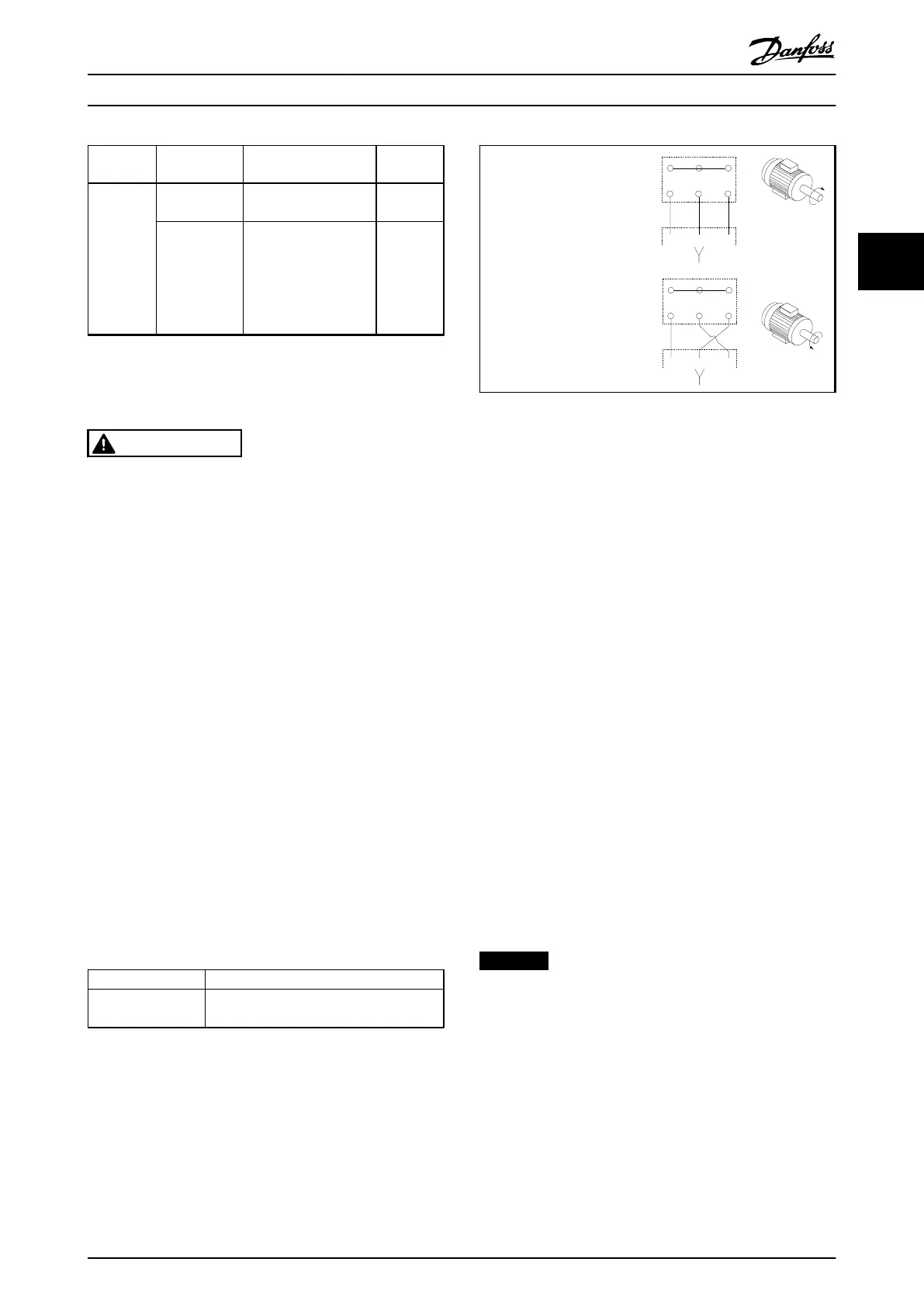
The motor must be connected to terminals U/T1/96, V/
T2/97, W/T3/98. Earth to terminal 99. All types of 3-phase
asynchronous standard motors can be used with a
frequency converter unit. The factory setting is for
clockwise rotation with the frequency converter output
connected as follows:
Terminal No. Function
96, 97, 98, 99 Mains U/T1, V/T2, W/T3
Earth
Table 3.19 Mains Terminals
•
Terminal U/T1/96 connected
to U-phase
•
Terminal V/T2/97 connected
to V-phase
•
Terminal W/T3/98
connected to W-phase
175HA036.11
U
1
V
1
W
1
96 97 98
FC
Motor
U
2
V
2
W
2
U
1
V
1
W
1
96 97 98
FC
Motor
U
2
V
2
W
2
Table 3.20
The direction of rotation can be changed by switching 2 phases in
the motor cable or by changing the setting of 4-10 Motor Speed
Direction.
Motor rotation check can be performed using 1-28 Motor
Rotation Check and following the steps shown in the
display.
F enclosure requirements
F1/F3 requirements: Motor phase cable quantities must be
multiples of 2, resulting in 2, 4, 6, or 8 (1 cable is not
allowed) to obtain equal amount of wires attached to both
inverter module terminals. The cables are required to be
equal length within 10% between the inverter module
terminals and the first common point of a phase. The
recommended common point is the motor terminals.
F2/F4 requirements: Motor phase cable quantities must be
multiples of 3, resulting in 3, 6, 9, or 12 (1 or 2 cables are
not allowed) to obtain equal amount of wires attached to
each inverter module terminal. The wires are required to
be equal length within 10% between the inverter module
terminals and the first common point of a phase. The
recommended common point is the motor terminals.
Output junction box requirements: The length, minimum
2.5 m, and quantity of cables must be equal from each
inverter module to the common terminal in the junction
box.
NOTICE
If a retrofit application requires unequal amount of wires
per phase, consult the factory for requirements and
documentation or use the top/bottom entry side cabinet
option.
How to Install
VLT
®
Automation Drive FC 300 Operating Instructions
MG33U402 - Rev. 2013-12-16 55
3 3

 Loading...


