4 How to Programme
4.1 The Graphical and Numerical LCP
The easiest programming of the frequency converter is
performed by the graphical LCP (LCP 102). Consult the
frequency converter Design Guide, when using the Numeric
Local Control Panel (LCP 101).
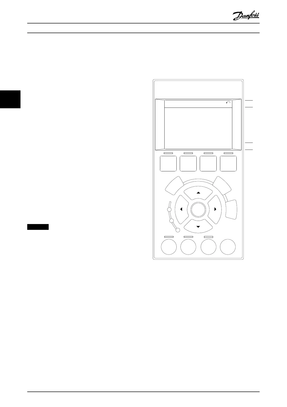
The control panel is divided into 4 functional groups:
1. Graphical display with Status lines.
2. Menu keys and indicator lights - changing
parameters and switching between display
functions.
3. Navigation keys and indicator lights (LEDs).
4. Operation keys and indicator lights (LEDs).
All data is displayed in a graphical LCP display, which can
show up to 5 items of operating data while displaying
[Status].
Display lines:
a.
Status line: Status messages displaying icons and
graphic.
b.
Line 1-2: Operator data lines displaying data
defined or selected by the user. By pressing
[Status], up to one extra line can be added.
c.
Status line: Status messages displaying text.
NOTICE
If some operation is delaying the start-up, the LCP
displays the INITIALISING message until it is ready.
Adding or removing options may delay the start-up.
Auto
on
Reset
Hand
on
O
Status
Quick
Menu
Main
Menu
Alarm
Log
Back
Cancel
Info
OK
Status
1(0)
1234rpm 10,4A 43,5Hz
Run OK
43,5Hz
On
Alarm
Warn.
130BA018.13
1
2
3
4
b
a
c
Illustration 4.1 Control Panel (LCP)
How to Programme
VLT
®
Automation Drive FC 300 Operating Instructions
80 MG33U402 - Rev. 2013-12-16
44

 Loading...


