Safe stop Terminal 37
3)
(Terminal 37 is fixed PNP logic)
Voltage level 0 - 24 V DC
Voltage level, logic'0' PNP < 4 V DC
Voltage level, logic'1' PNP >20 V DC
Nominal input current at 24 V 50 mA rms
Nominal input current at 20 V 60 mA rms
Input capacitance 400 nF
All digital inputs are galvanically isolated from the supply voltage (PELV) and other high-voltage terminals.
1)
Terminals 27 and 29 can also be programmed as output.
2)
Except safe stop input Terminal 37.
3)
See chapter 2.1.9 Safe Torque Off (STO) for further information about terminal 37 and Safe Stop..
Analog inputs
Number of analog inputs 2
Terminal number 53, 54
Modes Voltage or current
Mode select Switch S201 and switch S202
Voltage mode Switch S201/switch S202 = OFF (U)
Voltage level -10 to +10 V (scaleable)
Input resistance, R
i
approx. 10 kΩ
Max. voltage ± 20 V
Current mode Switch S201/switch S202 = ON (I)
Current level 0/4 to 20 mA (scaleable)
Input resistance, R
i
approx. 200 Ω
Max. current 30 mA
Resolution for analog inputs 10 bit (+ sign)
Accuracy of analog inputs Max. error 0.5% of full scale
Bandwidth 100 Hz
The analog inputs are galvanically isolated from the supply voltage (PELV) and other high-voltage terminals.
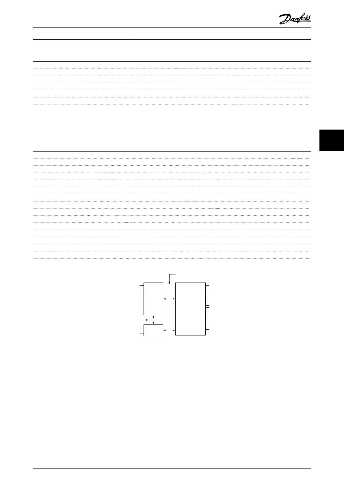
Mains
Functional
isolation
PELV isolation
Motor
DC-Bus
High
voltage
Control
+24V
RS485
18
37
130BA117.10
Illustration 5.1
General Specifications
VLT
®
Automation Drive FC 300 Operating Instructions
MG33U402 - Rev. 2013-12-16 91
5 5

 Loading...


