130BD901.10
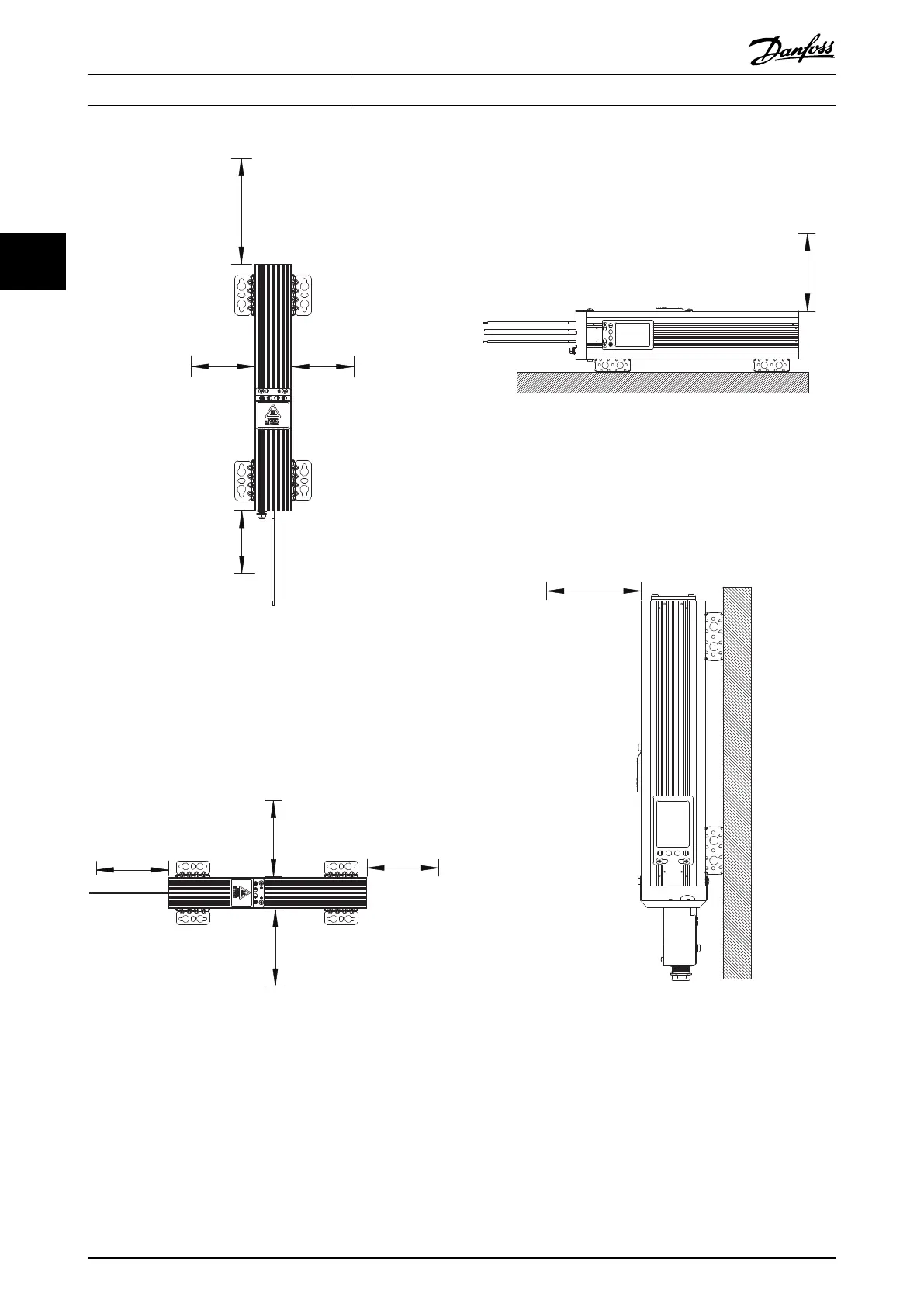
200 mm
500 mm
200 mm
200 mm
Illustration 3.2 Vertical Mounting, IP54
Versions with Fixed Cables
Horizontal mounting, IP54
For minimum clearances for horizontal mounting for all
aluminium-housed compact and flat-pack brake resistors,
see Illustration 3.3 (top view).
200 mm
200 mm
200 mm200 mm
130BD902.10
Illustration 3.3 Horizontal mounting, IP54
Versions with Fixed Cables
For minimum clearances for horizontal mounting for all
aluminium-housed compact and flat-pack brake resistors,
IP54 versions (versions with fixed cables), see Illustration 3.4
(side view).
Illustration 3.4 Horizontal mounting, IP54
Versions with Fixed Cables
Vertical mounting, IP21 and IP65
For minimum clearances for vertical mounting for all
aluminium-housed compact brake resistors, see
Illustration 3.5 and Illustration 3.6.
Illustration 3.5 Vertical Mounting, IP21 and IP65
Versions with Connection Box
Installation Design Guide
8 Danfoss A/S © Rev. 05/2014 All rights reserved. MG90O202
33

 Loading...

