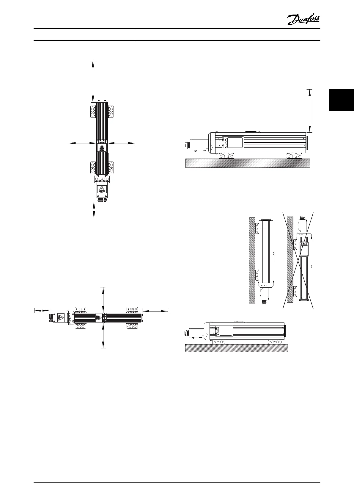
200 mm
200 mm
500 mm
100 mm
130BD905.10
Illustration 3.6 Vertical Mounting, IP21 and IP65
Versions with Connection Box
Horizontal mounting, IP21 and IP65
For minimum clearances for horizontal mounting for all
aluminium-housed compact brake resistors, see
Illustration 3.7 (top view).
200 mm
100 mm
200 mm
200 mm
130BD906.10
Illustration 3.7 Horizontal Mounting, IP21 and IP65
Versions with Connection Box
Horizontal mounting, IP21 and IP65
For minimum clearances for horizontal mounting for all
aluminium housed compact brake resistors, see
Illustration 3.8 (side view).
Illustration 3.8 Horizontal Mounting, IP21 and IP65
Versions with Connection Box
Orientation, compact and flat-pack brake resistors
Illustration 3.9 Orientation of Compact and Flat-pack Brake
Resistors
Derating with 20% is required when mounting the
compact brake resistors horizontally. The enclosure
protection of the IP21 types is reduced to IP20 when
mounted horizontally.
Installation
Design Guide
MG90O202 Danfoss A/S © Rev. 05/2014 All rights reserved. 9
3 3

 Loading...

