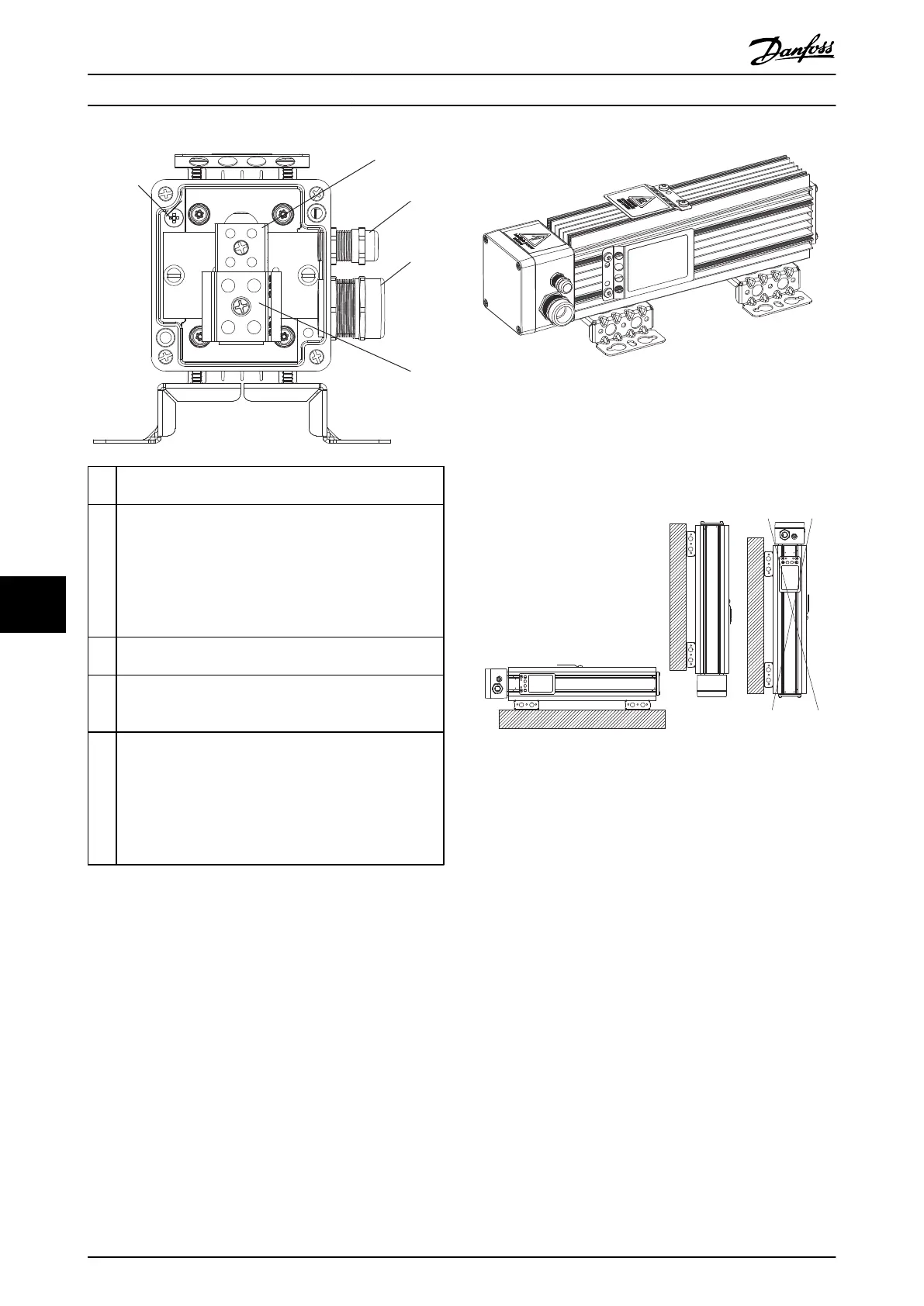
1 PE M4
Torque 2–3 Nm (17.71-26.57 lb-in)
2 Temperature switch connection:
Marked T1/T2
Type: Phoenix G5/2 with screw connection
IEC: 0.2-4 mm
2
/500 V
UL: AWG 24-12/300 V
Wire Stripping: 8 mm (0.31 in)
Torque: 0.7 Nm (6.2 lb-in)
3 For temperature switch cable:
Clamping Range: 3.5–7.0 mm (0.14–0.28 lb-in)
4 For resistor cable:
Cable gland with internal connection for braid
Clamping Range: 9.0–16.5 mm (0.35–0.65 in)
5 Resistor connection:
Marked RB1/RB2
Type: PHOENIX G10/2
IEC: 0.5-10 mm
2
/800 V
UL: AWG 20–6/600 V
Wire Stripping: 12 mm (0.47 in)
Torque: 1.5–1.8 Nm (13.28-15.94 lb-in)
Illustration 9.32 Connection Box
Illustration 9.33 IP65, 3D View
Mechanical mounting (see Illustration 9.34):
•
Vertical with connection box down, or
•
Horizontal
Illustration 9.34 Mechanical Mounting
Specifications Design Guide
100 Danfoss A/S © Rev. 05/2014 All rights reserved. MG90O202
99

 Loading...

