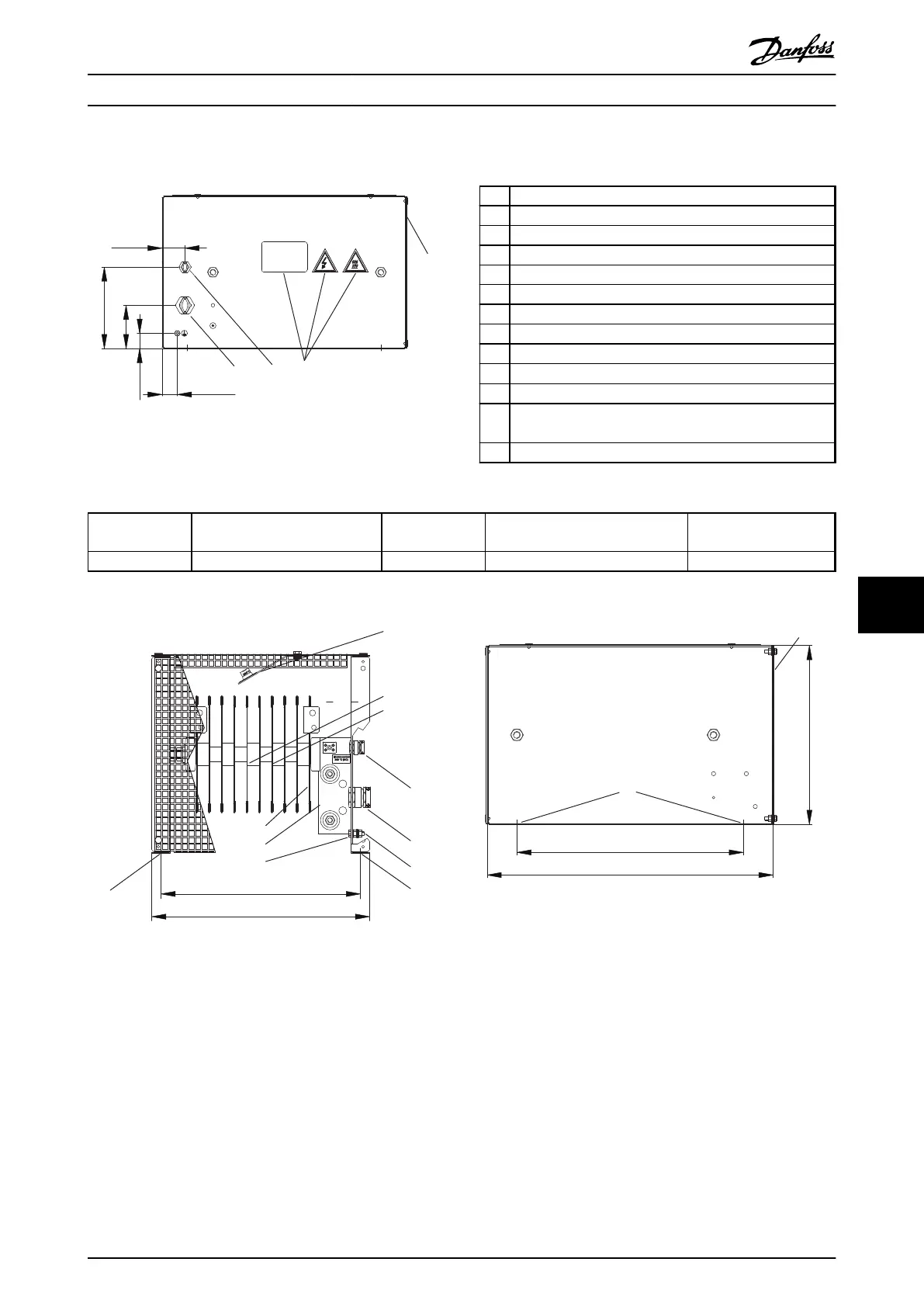
9.7.8 Figure 8 - 917CM13
175Uxxxx
6
8
3 4
30 [ 1.2 ]
45 [1.8]
160 [6.3]
85 [3.3]
30 [1.2]
130BD246.10
Illustration 9.39 IP20, Side View, Right
1 Resistor
2
Terminal board, see Illustration 9.42
3 Cable gland for load cables
4 Cable gland M16 temperature switch cable
5 Grounding bolt M6
6 Name plate/warning signs
7 Front cover IP20
8 Rear cover IP20
9 Top cover IP20
10
Temperature switch 260 °C (NC)
11 Load connection, 2x bolt M8
12 Auxiliary connection for temperature switch, porcelain
clamp 2.5 mm
2
13 4x fixing hole Ø 9 mm
Table 9.15 Legend to Illustration 9.39 to Illustration 9.43
Danfoss P/N Type code
Resistance
[Ω]
Cable gland type for load
terminals
Weight
[kg]
175u3236 MCE101C38R0P5K00E20BAW 38 M25 15
Table 9.16 Mechanical Dimensions
130BD247.10
1
2
302 [ 11.9 ]
330 [ 13.0 ]
2
3
4
5
7
10
13
13
1
5
7
Illustration 9.40 IP20, Front View
130BD248.10
380 [ 15.0 ]
300 [ 11.8 ]
480 [ 18.9 ]
13
7
Illustration 9.41 IP20, Side View, Left
Specifications Design Guide
MG90O202 Danfoss A/S © Rev. 05/2014 All rights reserved. 103
9 9

 Loading...

