1.5 Acoustic Noise or Vibration
If the compressor is making noise or vibrations at certain frequencies, try the following:
•
Speed Bypass, parameter group 4-6* Speed Bypass
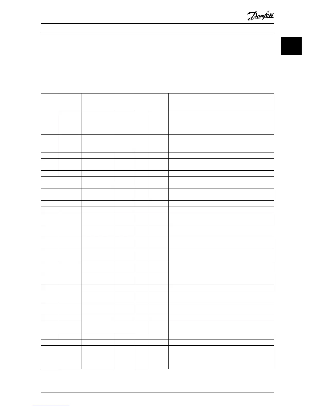
1.6 Warnings and Alarms
Fault
number
Alarm/
Warning Bit
Number
Fault text Warning Alarm Trip
locked
Cause of problem
2 16 Live zero error X X
Signal on terminal 53 or 54 is less than 50% of the value set
in 6-10 Terminal 53 Low Voltage, 6-12 Terminal 53 Low Current,
6-20 Terminal 54 Low Voltageor 6-22 Terminal 54 Low Current.
See also parameter group 6-0* Analog I/O Mode.
4 14 Mains ph. loss X X X
Missing phase on the supply side or too high voltage
imbalance. Check the supply voltage. See 14-12 Function at
Mains Imbalance.
7 11 DC over volt X X Intermediate circuit voltage exceeds limit.
8 10 DC under volt X X
Intermediate circuit voltage drops below “voltage warning
low” limit.
9 9 Inverter overload X X More than 100% load for too long.
10 8 Motor ETR over X X
The motor is too hot due to more than 100% load for too
long. See 1-90 Motor Thermal Protection
11 7 Motor th over X X
The thermistor or the thermistor connection is disconnected.
See 1-90 Motor Thermal Protection.
13 5 Over Current X X X Inverter peak current limit is exceeded.
14 2 Earth Fault X X Discharge from output phases to ground.
16 12 Short Circuit X X
Short-circuit in the compressor or on the compressor
terminals.
17 4 Ctrl. word TO X X
No communication to the frequency converter. See
parameter group 8-0* General Settings.
18 Start failed X
The speed has not been able to exceed 1-78 Compressor Start
Min Speed [Hz] during start within the allowed time.
30 19 U phase loss X X
Motor phase U is missing. Check the phase. See 4-58 Missing
Motor Phase Function.
31 20 V phase loss X X
Motor phase V is missing. Check the phase. See 4-58 Missing
Motor Phase Function.
32 21 W phase loss X X
Motor phase W is missing. Check the phase. See 4-58 Missing
Motor Phase Function.
38 17 Internal fault X X Contact the local Danfoss supplier.
44 28 Earth Fault X X
Discharge from output phases to ground, using the value of
15-31 Alarm Log Value if possible.
47 23
Control Voltage
Fault
X X X
24 V DC may be overloaded.
48 25 VDD1 supply low X X Control voltage low. Contact the local Danfoss supplier
49 X
The speed is below the specified limit in 1-87 Compressor
Min. Speed for Trip [Hz].
58 AMA internal X X Contact the local Danfoss supplier.
59 25 Current limit X
The current is higher than the value in 4-18 Current Limit.
60 44 External Interlock X
External interlock has been activated. To resume normal
operation, apply 24 V DC to the terminal programmed for
external interlock and reset the frequency converter (via
serial communication, digital I/O, or by pressing [Off/Reset]).
Quick Guide Quick Guide
MG18M102 Danfoss A/S © Rev. 09/2014 All rights reserved. 23
1
1
 Loading...


