3-10 Preset Reference
Range: Function:
selecting dedicated references,
select preset reference bit 0/1/2 [16],
[17], or [18] for the corresponding
digital inputs in parameter group
5-1* Digital Inputs.
3-11 Jog Speed [Hz]
Range: Function:
30 Hz* [ 0 - 500.0
Hz]
The jog speed is a xed output
speed at which the frequency
converter is running when the jog
function is activated.
See also parameter 3-80 Jog Ramp
Time.
3-14 Preset Relative Reference
Dene the xed value in %.
Range: Function:
0 %* [-100 -
100 %]
The sum of xed and variable
values (labeled Y in Illustration 3.3)
is multiplied by actual reference
(labeled X in Illustration 3.3). This
product is added to actual
reference X + X ×
Y
100
Relative
Z=X+X*Y/100
Resulting
actual
reference
Y
X
130BA059.12
Z
Illustration 3.3 Preset Relative
Reference
3-15 Reference 1 Source
Select the input to be used for the 1
st
reference signal.
Parameter 3-15 Reference 1 Source, parameter 3-16 Reference 2
Source, and parameter 3-17 Reference 3 Source dene up to 3
dierent reference signals. The sum of these reference signals
denes the actual reference.
Option: Function:
[0] No function
[1] * Analog Input
53
[2] Analog Input
54
[7] Pulse input 29
[11] Local bus
reference
3-16 Reference 2 Source
Select the input to be used for the 2
nd
reference signal.
Parameter 3-15 Reference 1 Source, parameter 3-16 Reference 2
Source, and parameter 3-17 Reference 3 Source dene up to 3
dierent reference signals. The sum of these reference signals
denes the actual reference. See also parameter 1-93 Thermistor
Source.
Option: Function:
[0] No function
[1] Analog Input
53
[2] * Analog Input
54
[7] Pulse input 29
[11] Local bus
reference
3-17 Reference 3 Source
Select the reference input to be used for the 3
rd
reference signal.
Parameter 3-15 Reference 1 Source, parameter 3-16 Reference 2
Source, and parameter 3-17 Reference 3 Source dene up to 3
dierent reference signals. The sum of these reference signals
denes the actual reference.
Option: Function:
[0] No function
[1] Analog Input
53
[2] Analog Input
54
[7] Pulse input 29
[11] * Local bus
reference
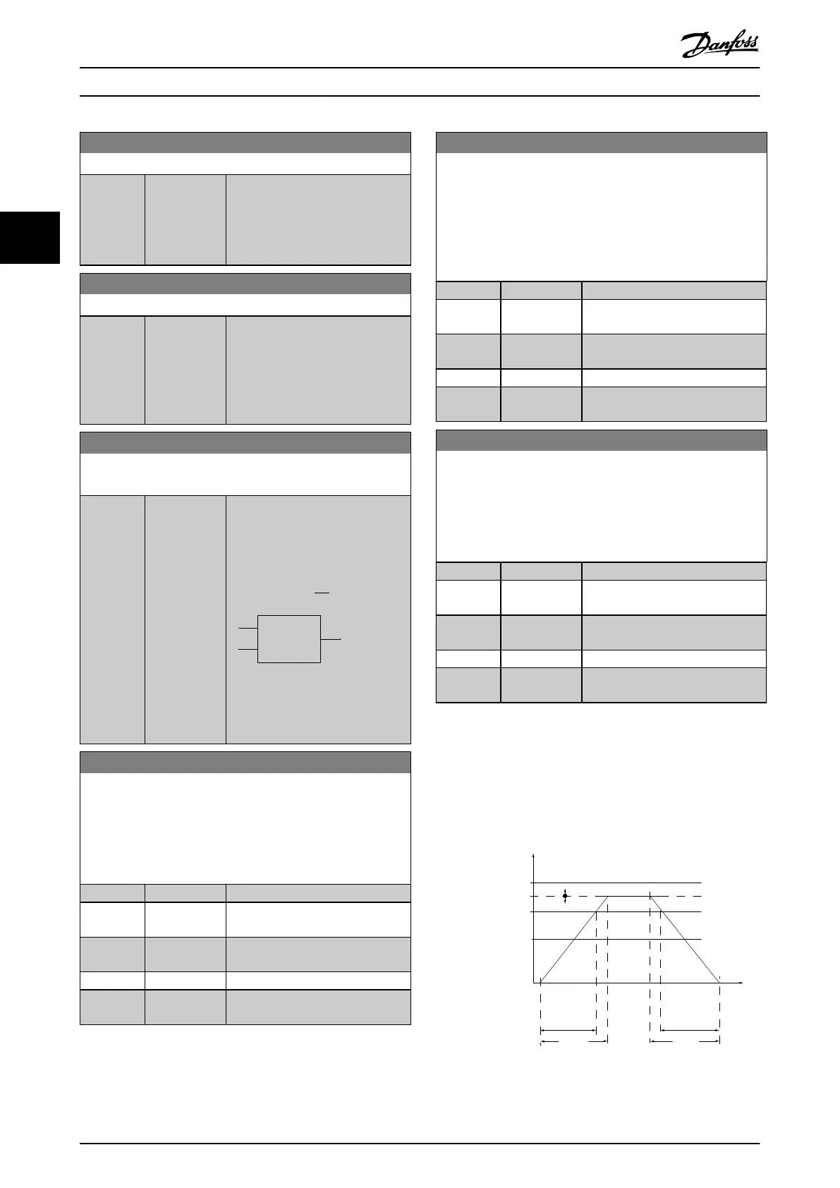
3.4.3 3-4* Ramp 1
Congure the ramp time parameters for each of the 2
ramps (parameter group 3-4* Ramp 1 and parameter group
3-5* Ramp 2). The ramp time is preset to the minimum
value of 10 ms for all power sizes.
t
acc
t
dec
130BB801.10
P 3-*2
Ramp (X)
Down
Time (Dec)
P 4-14
High-limit
RPM
Reference
P 1-23
Motor
frequency
P 4-12
Low limit
Time
P 3-*1
Ramp (X)Up
Time (Acc)
Illustration 3.4 Ramps
Parameters
VLT
®
Compressor Drive CDS 803
24 Danfoss A/S © 06/2019 All rights reserved. MG18P202
33
 Loading...


