5-40 Function Relay
Array (Relay 1 [0], Relay 2 [1])
Select options to dene the function of the relays.
The selection of each mechanical relay is realized in an array
parameter.
Option: Function:
clockwise (the logical product of
the status bits running AND reverse).
[165] Local ref.
active
The output is high when
parameter 3-13 Reference Site=[2]
Local or when
parameter 3-13 Reference Site=[0]
Linked to hand auto at the same
time as the LCP is in [Hand on]
mode.
[166] Remote ref.
active
The output is high when
parameter 3-13 Reference Site is set
to [0] Linked to Hand / Auto or [1]
Remote, while the LCP is in Auto on
mode.
[167] Start
command
activ
The output is high when there is an
active start command (that is, via
digital input, bus connection, [Hand
on] or [Auto on], and no stop
command is active.
[168] Drive in hand
mode
The output is high when the
frequency converter is in Auto on
mode (as indicated by the LED light
above [Hand on].
[169] Drive in auto
mode
The output is high when the
frequency converter is in Auto on
mode (as indicated by the LED light
above [Auto on].
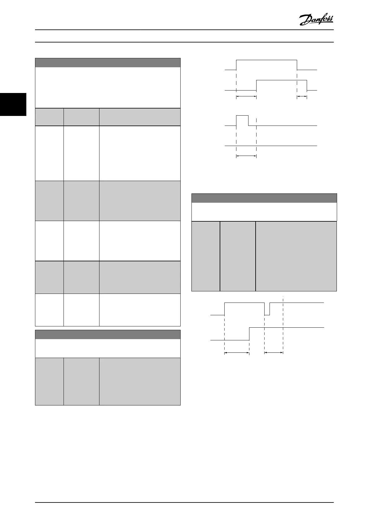
5-41 On Delay, Relay
Array [2], (Relay 1 [0], Relay 2 [1])
Range: Function:
0.01 s* [0 - 600 s] Enter the delay of the relay cut in
time. Select one of 2 internal
mechanical relays in an array
function. See
parameter 5-40 Function Relay for
details.
Selected
Event
Relay
output
Selected
Event
Relay
output
On Delay
P 5-41
On Delay
P 5-41
O Delay
P 5-42
130BA171.10
Illustration 3.5 On Delay, Relay
5-42 O Delay, Relay
Array[2]: Relay1[0], Relay2[1]
Range: Function:
0.01 s* [0 - 600 s] Enter the delay of the relay cut out
time. Select one of 2 internal
mechanical relays in an array
function. See
parameter 5-40 Function Relay for
details. If the selected event
condition changes before a delay
timer expires, the relay output is
unaected.
Selected
Event
Relay
output
On Delay
P 5-41
O Delay
P 5-42
130BA172.10
Illustration 3.6 O Delay, Relay
If the selected event condition changes before the on
delay or o delay timer expires, the relay output is
unaected.
3.6.4 5-5* Pulse Input
The pulse input parameters are used to dene an
appropriate window for the impulse reference area by
conguring the scaling and lter settings for the pulse
inputs. Input terminals 29 or 33 act as frequency reference
inputs. Set terminal 29 (parameter 5-13 Terminal 29 Digital
Input) or terminal 33 (parameter 5-15 Terminal 33 Digital
Parameters
VLT
®
Compressor Drive CDS 803
34 Danfoss A/S © 06/2019 All rights reserved. MG18P202
33

 Loading...


