3.3.3 Inverter Section
In the inverter section (see Figure 3.7), gate signals are
delivered from the control card, through the power card
and gate drive card to the gates of the IGBTs. The series
connection of each set of IGBTs is delivered to the output,
first passing through the current sensors.
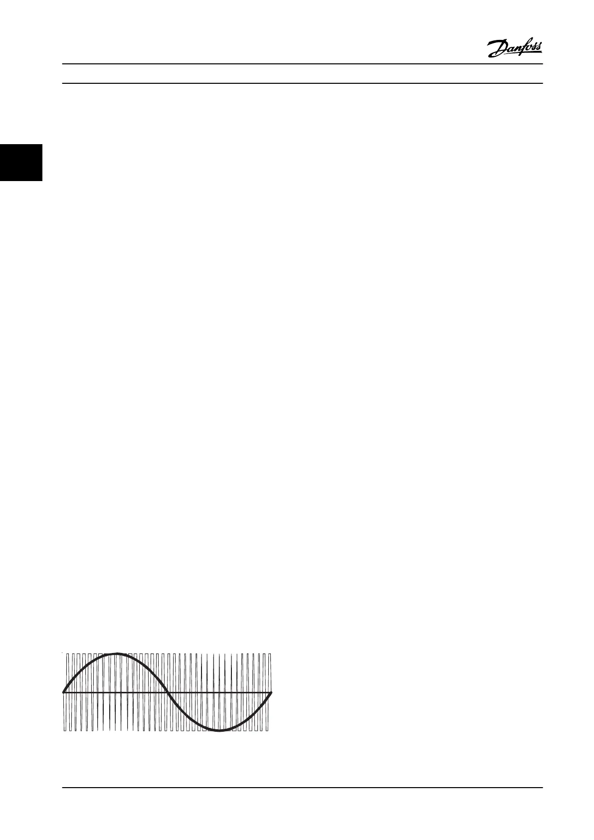
Once a run command and speed reference are present, the
IGBTs begin switching to create the output waveform, as
shown in Figure 3.6. Looking at the phase-to-phase voltage
waveform with an oscilloscope, the pulse width
modulation (PWM) principal creates a series of pulses
which vary in width. Basically, the pulses are narrower as
zero crossing is approached and wider the farther from
zero crossing. The pulse duration of applied DC voltage
controls the width. Although the voltage waveform is a
consistent amplitude, the inductance within the motor
windings averages the voltage delivered so, as the pulse
width of the waveform varies, the average voltage the
motor detects also varies. The resultant current waveform
takes on the sine wave shape common to an AC system.
The rate at which the pulses occur determines the
frequency of the waveform. By employing a sophisticated
control scheme, the adjustable frequency drive delivers a
current waveform that nearly replicates a true AC sine
wave.
Hall effect current sensors monitor the output current and
deliver proportional signals to the power card where they
are buffered and delivered to the control card. The control
card logic uses these current signals to determine proper
waveform compensations based on load conditions. They
further serve to detect overcurrent conditions, including
ground faults and phase-to-phase shorts on the output.
During normal operation, the power card and control card
are monitoring various functions within the adjustable
frequency drive. The current sensors provide current
feedback information. The DC bus voltage is monitored as
well as the voltage delivered to the motor. A thermal
sensor mounted inside each IGBT module provides
heatsink temperature feedback.
Figure 3.6 Output Voltage and Current Waveforms
Internal Adjustable Frequen... Service Manual
40 Danfoss A/S © Rev. 2014-02-10 All rights reserved. MG94A222
33

 Loading...


