EasyManuals Logo
Home>Danfoss>DC Drives>VLT FC 100

Danfoss VLT FC 100 Operating Instructions

Danfoss VLT FC 100
113 pages
To Next Page IconTo Next Page
To Previous Page IconTo Previous Page
Page #20 background imageLoading...
Page #20 background image
Terminal locations - Rectifier (F10, F11, F12 and F13)
1
239.6 [ 9.43 ]
0.0 [ 0.00 ]
0.0 [ 0.00 ]
160.0 [ 6.30 ]
56.6 [ 2.23 ]
39.8 [ 1.57 ]
91.8 [ 3.61 ]
174.1 [ 6.85 ]
226.1 [ 8.90 ]
130BB534.10
R2/L12
R1/L11
91-1
91
S2/L22
S1/L21
92-1
T2/L32 93-1
92
T1/L31 93
U/T1 96 V/T2 97 W/T3 98
0.0 [ 0.00 ]
57.6 [ 2.27 ]
74.0 [ 2.91 ]
100.4 [ 3.95 ]
139.4 [ 5.49 ]
172.6 [ 6.80 ]
189.0 [ 7.44 ]
199.4 [ 7.85 ]
287.6 [ 11.32 ]
304.0 [ 11.97 ]
407.3 [ 16.04 ]
464.4 [ 18.28 ]
522.3 [ 20.56 ]
524.4 [ 20.65 ]
629.7 [ 24.79 ]
637.3 [ 25.09 ]
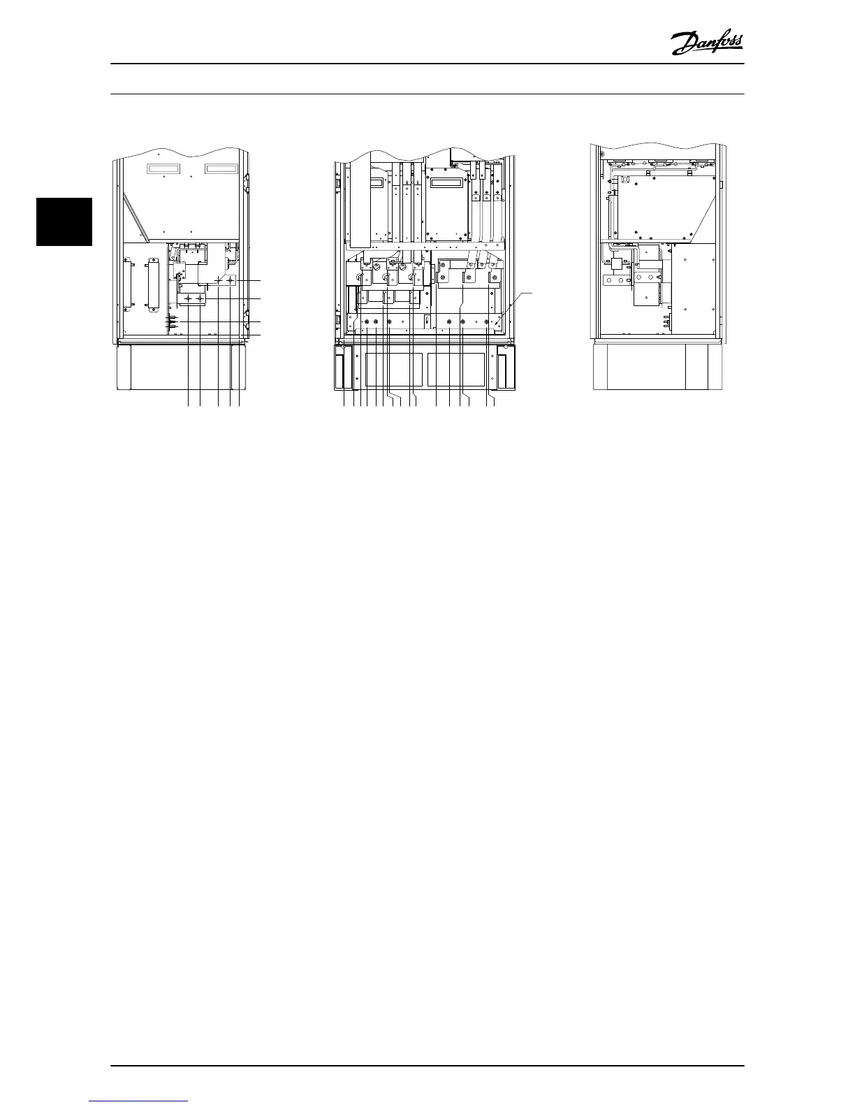
Illustration 3.15 Terminal locations - Rectifier (Left side, front and right side view). The gland plate is 42 mm below .0 level.
1) Loadshare Terminal (-)
2) Earth ground bar
3) Loadshare Terminal (+)
How to Install
VLT
®
Automation Drive FC 300 12-Pulse
Operating Instructions High Power
20 MG34Q202 - VLT
®
is a registered Danfoss trademark
3
3

Other manuals for Danfoss VLT FC 100

Questions and Answers:

Question and Answer IconNeed help?

Do you have a question about the Danfoss VLT FC 100 and is the answer not in the manual?

Danfoss VLT FC 100 Specifications

General IconGeneral
BrandDanfoss
ModelVLT FC 100
CategoryDC Drives
LanguageEnglish

Related product manuals