EasyManuals Logo

Danfoss VLT FC Series Installation Guide

Danfoss VLT FC Series
12 pages
To Next Page IconTo Next Page
To Previous Page IconTo Previous Page
Page #9 background imageLoading...
Page #9 background image
9. Remove the control card EMC shield.
A If the MCB 159 is installed, lift the left side of the control card EMC shield first, then lift the right side until it is possible to
remove the MCB 159 ribbon cable. Otherwise, there is a risk to destroy the cable or the connector. When the ribbon cable is
removed, the EMC shield is separated from the control card.
2
1
e30bf723.11
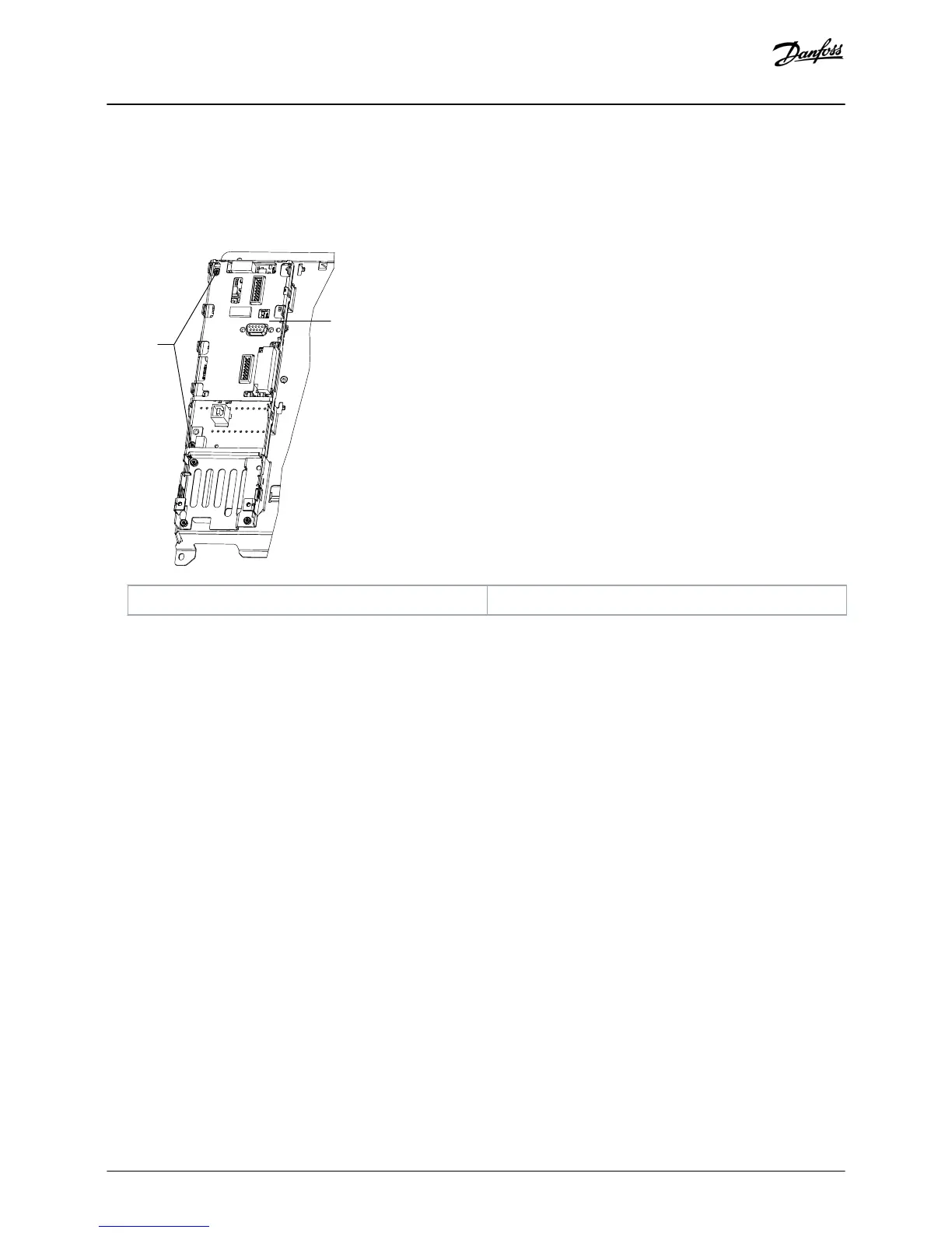
1 T10 screws 2 Control card
Illustration 8: Screws and EMC Shield
10. Unscrew the 3 T10 screws and remove them.
11. Gently remove the control card from the upper-right socket. Avoid overbending and contact with electronic components.
Replacement
Installation Guide | Control Card VLT® FC Series
AN279051429263en-000101 / 130R0788 | 9
Danfoss A/S © 2018.09

Other manuals for Danfoss VLT FC Series

Questions and Answers:

Question and Answer IconNeed help?

Do you have a question about the Danfoss VLT FC Series and is the answer not in the manual?

Danfoss VLT FC Series Specifications

General IconGeneral
CategoryDC Drives
SeriesVLT FC Series
Output Voltage0-100% of input voltage
Protection FeaturesOvervoltage, Undervoltage, Overcurrent, Short circuit, Overtemperature, Motor overload
Communication InterfacesCANopen, PROFIBUS, Ethernet
Cooling Methodliquid-cooled
Enclosure RatingIP20, IP21, IP55
Ambient Temperature-10°C to +40°C (14°F to 104°F) without derating

Related product manuals