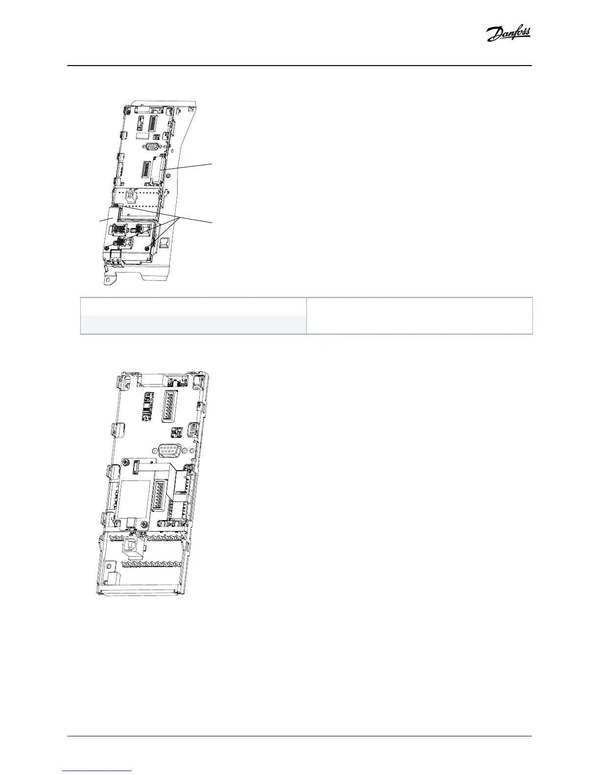
EasyManuals Logo

Danfoss VLT FC Series Installation Guide

Danfoss VLT FC Series
12 pages
To Next Page IconTo Next Page
To Previous Page IconTo Previous Page
Page #8 background imageLoading...
Page #8 background image
1
3
2
e30bf722.11
1 Cable shield
3 T10 screws
2 MCO ribbon cable
Illustration 6: Location of the Cable Shield, Screws, and MCO Ribbon Cable (Control Card without MCB 159)
e30bg832.10
Illustration 7: Control Card with MCB 159
8. Unscrew the 2 T10 screws holding the control card EMC shield (4 screws if MCO is installed).
A If MCO is installed, remove the MCO ribbon cable.
B If the VLT® Sensorless Safety MCB 159 option is installed, it is not possible to remove the ribbon cable before removing the
control card EMC shield.
Replacement
Installation Guide | Control Card VLT® FC Series
AN279051429263en-000101 / 130R0788
8 | Danfoss A/S © 2018.09

Other manuals for Danfoss VLT FC Series

Questions and Answers:

Question and Answer IconNeed help?

Do you have a question about the Danfoss VLT FC Series and is the answer not in the manual?

Danfoss VLT FC Series Specifications

General IconGeneral
CategoryDC Drives
SeriesVLT FC Series
Output Voltage0-100% of input voltage
Protection FeaturesOvervoltage, Undervoltage, Overcurrent, Short circuit, Overtemperature, Motor overload
Communication InterfacesCANopen, PROFIBUS, Ethernet
Cooling Methodliquid-cooled
Enclosure RatingIP20, IP21, IP55
Ambient Temperature-10°C to +40°C (14°F to 104°F) without derating

Related product manuals