NOTE!
Where Live Zero Monitoring is used, it is important that any analog inputs not being used for the frequency controller, i.e., being used
as part of the building management system decentral I/O, should have their Live Zero function disabled.
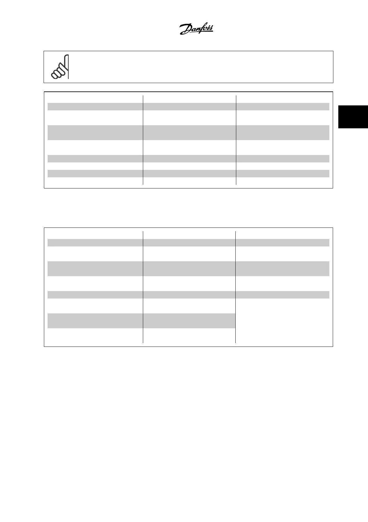
Terminal Parameters Terminal Parameters Terminal Parameters
Analog inputs Analog inputs Relays
X42/1 par.26-00
Terminal X42/1
Mode
, 26-1*
53 6-1* Relay 1 Term 1, 2, 3 5-4*
X42/3 par.26-01
Terminal X42/3
Mode
, 26-2*
54 6-2* Relay 2 Term 4, 5, 6 5-4*
X42/5 par.26-02
Terminal X42/5
Mode
, 26-3*
Analog outputs Analog output
X42/7 26-4* 42 6-5*
X42/9 26-5*
X42/11 26-6*
Table 3.3: Relevant parameters
It is also possible to read the analog inputs, write to the analog outputs and control the relays, using communication via the serial bus. In this instance,
these are the relevant parameters.
Terminal Parameters
Terminal Parameters Terminal Parameters
Analog inputs (read) Analog inputs (read) Relays
X42/1 par.18-30
Analog Input
X42/1
53 par.16-62
Analog In-
put 53
Relay 1 Term 1, 2, 3 par.16-71
Relay Output
[bin]
X42/3 par.18-31
Analog Input
X42/3
54 par.16-64
Analog In-
put 54
Relay 2 Term 4, 5, 6 par.16-71
Relay Output
[bin]
X42/5 par.18-32
Analog Input
X42/5
Analog outputs (write) Analog output (write)
X42/7 par.18-33
Analog Out X42/7
[V]
42 par.6-53
Terminal 42
Output Bus Control
NOTE! The relay outputs must be enabled via
Control Word Bit 11 (Relay 1) and Bit 12 (Relay
2)
X42/9 par.18-34
Analog Out X42/9
[V]
X42/11 par.18-35
Analog Out
X42/11 [V]
Table 3.4: Relevant parameters
Setting of on-board Real Time Clock.
The Analog I/O option incorporates a real time clock with battery back-up. This can be used as a back-up of the clock function included in the adjustable
frequency drive as standard. See section Clock Settings, par. 0-7*.
The Analog I/O option can be used for the control of devices such as servos or valves, using the extended closed-loop facility, thus removing control from
the building management system. See section Parameters: Ext. Closed-loop – FC 100 par. 21-**. There are three independent closed-loop PID controllers.
VLT
®
HVAC Drive Programming Guide 3 Parameter Description
MG.11.C6.22 - VLT
®
is a registered Danfoss trademark
3-251
3

 Loading...


