Normal overload 110% for 1 minute
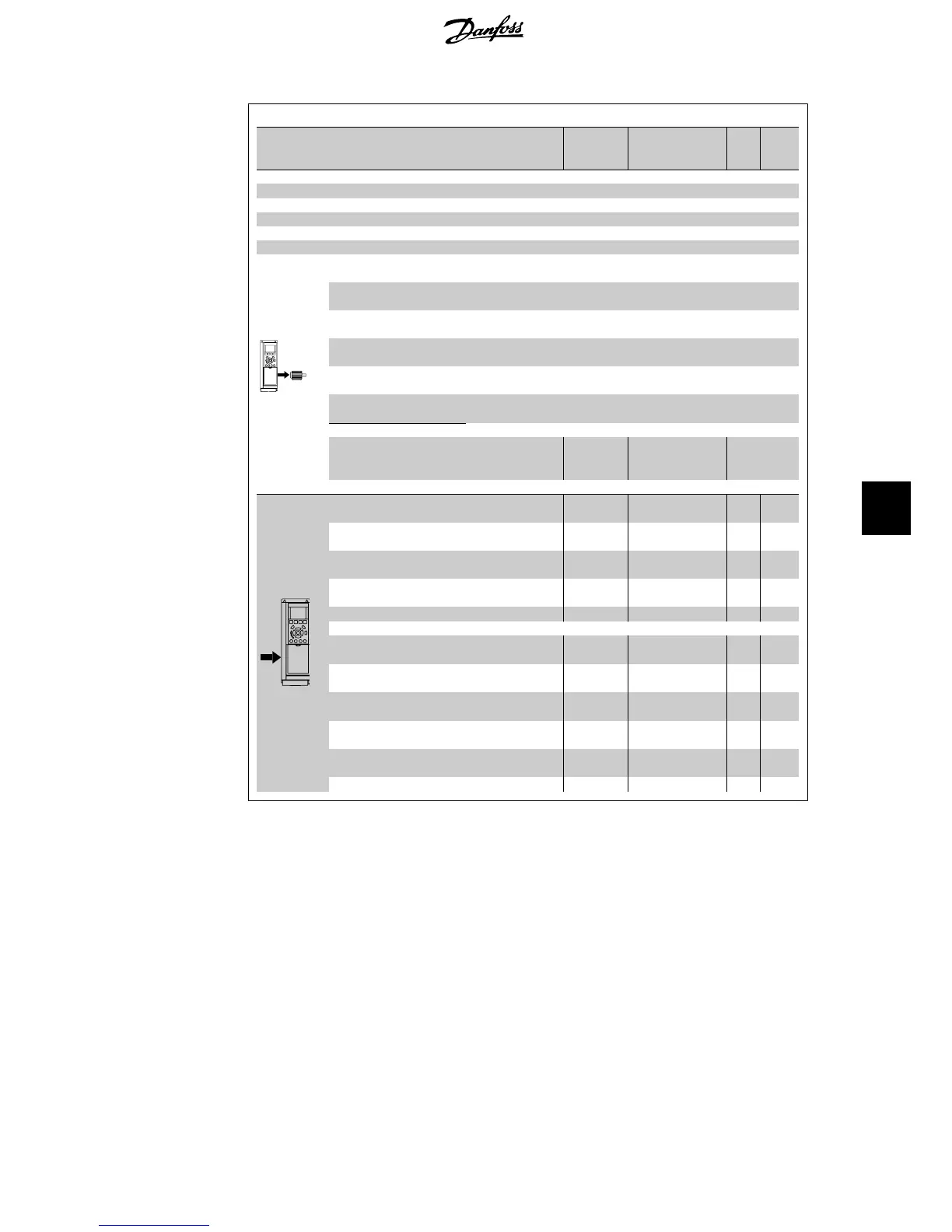
Frequency converter
Typical Shaft Output [kW]
P11K
11
P15
K
15
P18K
18.5
P22K
22
P30K
30
P37K
37
P45K
45
P55
K
55
P75K
75
P90K
90
Typical Shaft Output [HP] at 460 V 15 20 25 30 40 50 60 75 100 125
IP 20
IP 21 B1 B1 B1 B2 B2 C1 C1 C1 C2 C2
IP 55 B1 B1 B1 B2 B2 C1 C1 C1 C2 C2
IP 66 B1 B1 B1 B2 B2 C1 C1 C1
Output current
Continuous
(3 x 380-440 V) [A]
24 32 37.5 44 61 73 90 106 147 177
Intermittent
(3 x 380-440 V) [A]
26.4 35.2 41.3 48.4 67.1 80.3 99 117 162 195
Continuous
(3 x 440-480 V) [A]
21 27 34 40 52 65 80 105 130 160
Intermittent
(3 x 440-480 V) [A]
23.1 29.7 37.4 44 61.6 71.5 88 116 143 176
Continuous kVA
(400 V AC) [kVA]
16.6 22.2 26 30.5 42.3 50.6 62.4 73.4 102 123
Continuous kVA
(460 V AC) [kVA]
16.7 21.5 27.1 31.9 41.4 51.8 63.7 83.7 104 128
Max. cable size:
(mains, motor, brake)
[[mm
2
/
AWG]
10/7 35/2 50/1/0 104 128
Max. input current
Continuous
(3 x 380-440 V ) [A]
22 29 34 40 55 66 82 96 133 161
Intermittent
(3 x 380-440 V ) [A]
24.2 31.9 37.4
44 60.5 72.6 90.2 106 146 177
Continuous
(3 x 440-480 V) [A]
19 25 31 36 47 59 73 95 118 145
Intermittent
(3 x 440-480 V) [A]
20.9 27.5 34.1
39.6 51.7 64.9 80.3 105 130 160
Max. pre-fuses
1)
[A]
63 63 63 63 80 100 125 160 250 250
Environment
Estimated power loss
at rated max. load [W]
4)
278 392 465 525 739 698 843 1083 1384 1474
Weight enclosure IP20
[kg]
Weight enclosure IP 21
[kg]
23 23 23 27 27 45 45 45 65 65
Weight enclosure IP 55
[kg]
23 23 23
27 27 45 45 45 65 65
Weight enclosure IP 66
[kg]
23 23 23 27 27 45 45 45 - -
Efficiency
4)
0.98 0.98 0.98 0.98 0.98 0.98 0.98 0.98 0.98 0.99
1. For type of fuse see section
Fuses
2. American Wire Gauge
3. Measured using 5 m screened motor cables at rated load and rated frequency
4. The typical power loss is at normal load conditions and expected to be within +/- 15%
(tolerance relates to variety in voltage and cable conditions).
Values are based on a typical motor efficiency (eff2/eff3 border line). Lower efficiency
motors will also add to the power loss in the frequency converter and vice versa.
If the switching frequency is raised from nominal the power losses may rise significantly.
LCP and typical control card power consumptions are included. Further options and cus-
tomer load may add up to 30W to the losses. (Though typically only 4W extra for a fully
loaded control card, or options for slot A or slot B, each).
Although measurements are made with state of the art equipment, some measurement
inaccuracy must be allowed for (+/- 5%).
VLT
®
HVAC Drive Operating Instructions 8. Specifications
MG.11.A4.02 - 09.10.06. VLT
®
is a registered Danfoss trademark
133
8
 Loading...


