Illustration 6.8: Step 7: Use the up/down naviga-
tion keys to select between the different choices.
Press [OK].
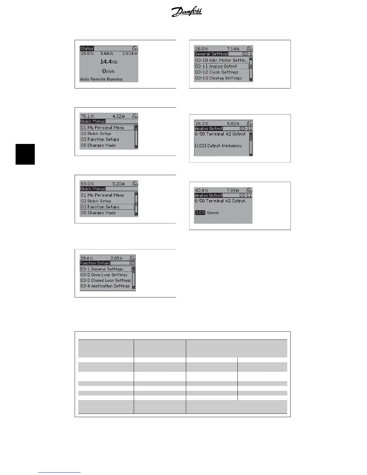
The Function Setup parameters are grouped in the following way:
Q3-1 General Settings
Q3-10 Adv. Motor Settings Q3-11 Analog Output Q3-12 Clock Settings Q3-13 Display Settings
1-90 Motor Thermal Protection 6-50 Terminal 42 Output 0-70 Set date and time 0-20 Display Line 1.1 Small
1-93 Thermistor Source 6-51 Terminal 42 Output
max. scale
0-71 Date format 0-21 Display Line 1.2 Small
1-29 Automatic Motor Adap-
tion
6-52 Terminal 42 Output
min. scale
0-72 Time format 0-22 Display Line 1.3 Small
14-01 Switching Frequency 0-74 DST/Summertime 0-23 Display Line 2 large
0-76 DST/Summertime start 0-24 Display Line 3 large
0-77 DST/Summertime end 0-37 Display Text 1
0-38 Display Text 2
0-39 Display Text 3
6. How to programme the frequency converter VLT
®
HVAC Drive Operating Instructions
60
MG.11.A4.02 - 09.10.06. VLT
®
is a registered Danfoss trademark
6