Function:
This function makes it possible to catch a mo-
tor which is spinning freely due to a mains
drop-out.
Description of choice:
Select
Disable
[0] if this function is not re-
quired.
Select
Enable
[1] to enable the frequency con-
verter to “catch” and control a spinning motor.
When par. 1-73 is enabled, par. 1-71
Start
Delay
has no function.
Search direction for flying start is linked to the
setting in par. 4-10, Motor Speed Direction.
Clockwise
[0]: Flying start search in clockwise
direction. If not successful, a DC brake is car-
ried out.
Both Directions
[2]: The flying start will first
make a search in the direction determined by
the last reference (direction). If not finding
the speed it will make a search in the other
direction. If not successful, a DC brake will be
activated in the time set in par. 2-02, Braking
Time. Start will then take place from 0 Hz.
1-80 Function at Stop
Value:
Coast [0]
DC hold/Preheat [1]
Function:
Select the frequency converter function after
a stop command or after the speed is ramped
down to the settings in par. 1-81
Min Speed
for Function at Stop [RPM]
.
Select
Coast
[0] to leave the motor in free
mode.
Select
DC hold/Preheat
[1] to energize the
motor with a DC holding current (see par.
2-00).
1-90 Motor Thermal Protection
Value:
No protection [0]
Thermistor warning [1]
Thermistor trip [2]
ETR warning 1 [3]
ETR trip 1 [4]
ETR warning 2 [5]
ETR trip 2 [6]
ETR warning 3 [7]
ETR trip 3 [8]
ETR warning 4 [9]
ETR trip 4 [10]
Function:
The frequency converter determines the mo-
tor temperature for motor protection in two
different ways:
• Via a thermistor sensor connected to
one of the analog or digital inputs
(par. 1-93
Thermistor Source
).
• Via calculation (ETR = Electronic
Thermal Relay) of the thermal load,
based on the actual load and time.
The calculated thermal load is com-
pared with the rated motor current
I
M,N
and the rated motor frequency
f
M,N
. The calculations estimate the
need for a lower load at lower speed
due to less cooling from the fan in-
corporated in the motor.
Select
No protection
[0] if the motor is con-
tinuously overloaded and no warning or trip of
frequency converter is wanted.
Select
Thermistor warning
[1] to activate a
warning when the connected thermistor in the
motor reacts in the event of motor over-tem-
perature.
Select
Thermistor trip
[2] to stop (trip) the
frequency converter when the connected
thermistor in the motor reacts in the event of
motor over-temperature.
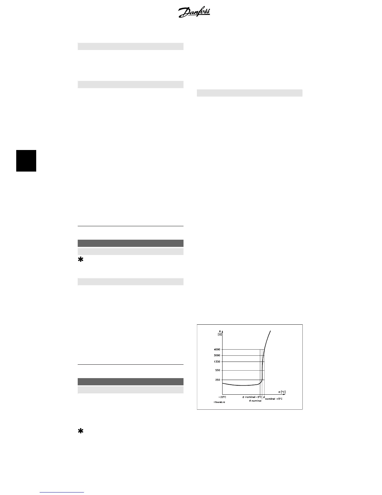
The thermistor cut-out value is > 3 k.
Integrate a thermistor (PTC sensor) in the
motor for winding protection.
Motor protection can be implemented using a
range of techniques: PTC sensor in motor
6. How to programme the frequency converter VLT
®
HVAC Drive Operating Instructions
68
MG.11.A4.02 - 09.10.06. VLT
®
is a registered Danfoss trademark
6

 Loading...


