windings; mechanical thermal switch (Klixon
type); or Electronic Thermal Relay (ETR).
Using a digital input and 24 V as power supply:
Example: The frequency converter trips when
the motor temperature is too high.
Parameter set-up:
Set Par. 1-90
Motor Thermal Protection
to
Thermistor Trip
[2]
Set Par. 1-93
Thermistor Source
to
Digital In-
put
[6]
Using a digital input and 10 V as power supply:
Example: The frequency converter trips when
the motor temperature is too high.
Parameter set-up:
Set Par. 1-90
Motor Thermal Protection
to
Thermistor Trip
[2]
Set Par. 1-93
Thermistor Source
to
Digital In-
put 33
[6]
Using an analog input and 10 V as power sup-
ply:
Example: The frequency converter trips when
the motor temperature is too high.
Parameter set-up:
Set Par. 1-90
Motor Thermal Protection
to
Thermistor Trip
[2]
Set Par. 1-93
Thermistor Source
to
Analog In-
put 54
[2]
Do not select a reference source.
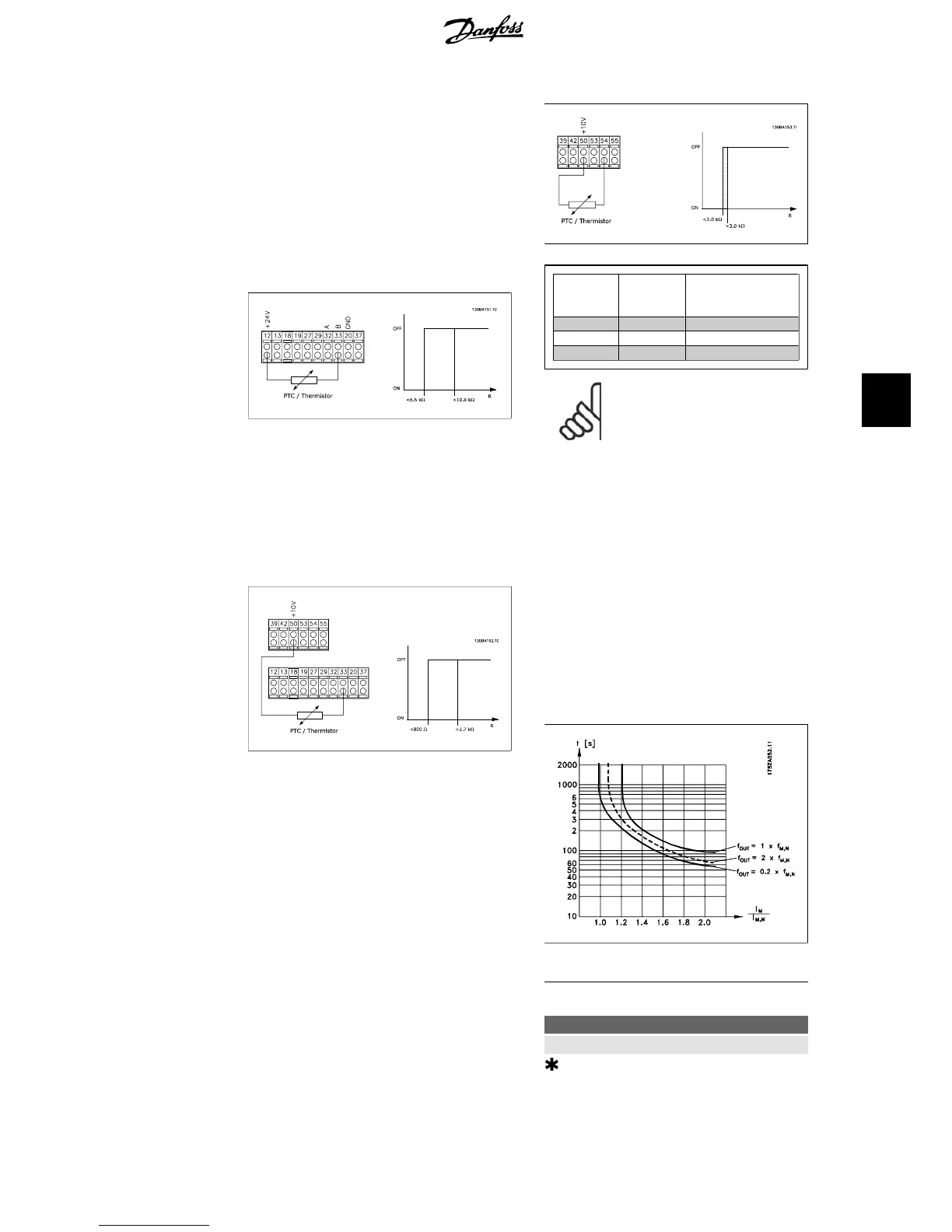
Input
Digital/an-
alog
Supply
Voltage
Volt
Threshold
Cut-out Values
Digital 24 V < 6.6 k - > 10.8 k
Digital 10 V < 800 - > 2.7 k
Analog 10 V < 3.0 k - > 3.0 k
NB!
Check that the chosen supply
voltage follows the specification
of the used thermistor element.
Select
ETR Warning 1-4
, to activate a warning
on the display when the motor is overloaded.
Select
ETR Trip 1-4
to trip the frequency con-
verter when the motor is overloaded.
Programme a warning signal via one of the
digital outputs. The signal appears in the
event of a warning and if the frequency con-
verter trips (thermal warning).
ETR (Electronic Thermal Relay) functions 1-4
will calculate the load when the set-up where
they were selected is active. For example ETR
starts calculating when setup 3 is selected. For
the North American market: The ETR func-
tions provide class 20 motor overload protec-
tion in accordance with NEC.
1-93 Thermistor Source
Value:
None [0]
Analog input 53 [1]
Analog input 54 [2]
VLT
®
HVAC Drive Operating Instructions 6. How to programme the frequency converter
MG.11.A4.02 - 09.10.06. VLT
®
is a registered Danfoss trademark
69
6

 Loading...


