Cascade Pump1 [211]
Cascade Pump2 [212]
Cascade Pump3 [213]
Fire Mode Active [220]
Fire Mode Coast [221]
Fire Mode Was Active [222]
Alarm, Trip Locked [223]
Bypass Mode Active [224]
Function:
Select options to define the function of the re-
lays.
The selection of each mechanical relay is re-
alised in an array parameter.
6-00 Live Zero Timeout Time
Value:
1 - 99 s
10s
Function:
Enter the Live Zero Time-out time period. Live
Zero Time-out Time is active for analog in-
puts, i.e. terminal 53 or terminal 54, allocated
to current and used as reference or feedback
sources. If the reference signal value associ-
ated with the selected current input falls be-
low 50% of the value set in par. 6-10, par.
6-12, par. 6-20 or par. 6-22 for a time period
longer than the time set in par. 6-00, the func-
tion selected in par. 6-01 will be activated.
6-01 Live Zero Timeout Function
Value:
Off [0]
Freeze output [1]
Stop [2]
Jogging [3]
Max. speed [4]
Stop and trip [5]
Function:
Select the time-out function. The function set
in par. 6-01 will be activated if the input signal
on terminal 53 or 54 is below 50% of the value
in par. 6-10, par. 6-12, par. 6-20 or par. 6-22
for a time period defined in par. 6-00. If sev-
eral time-outs occur simultaneously, the fre-
quency converter prioritises the time-out
functions as follows:
1. Par. 6-01
Live Zero Time-out Func-
tion
2. Par. 8-04
Control-word Time-out
Function
The output frequency of the frequency con-
verter can be:
• [1] frozen at the present value
• [2] overruled to stop
• [3] overruled to jog speed
• [4] overruled to max. speed
• [5] overruled to stop with subse-
quent trip
If you select set-up 1-4, par. 0-10,
Active Set-
up
, must be set to
Multi Set-up
, [9].
This parameter cannot be adjusted while the
motor is running.
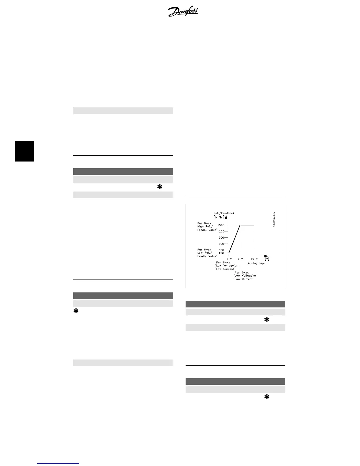
6-10 Terminal 53 Low Voltage
Value:
0.00 - par. 6-11
0.07V
Function:
Enter the low voltage value. This analog input
scaling value should correspond to the low
reference/feedback value set in par. 6-14.
6-11 Terminal 53 High Voltage
Value:
Par. 6-10 to 10.0 V
10.0V
6. How to programme the frequency converter VLT
®
HVAC Drive Operating Instructions
74
MG.11.A4.02 - 09.10.06. VLT
®
is a registered Danfoss trademark
6