3.3.3 Mounting
To mount the bus decoupling kit:
1. Place the horizontal decoupling plate on the
control cassette that is mounted on the
frequency converter, and fasten the plate using 2
screws, as shown in Illustration 3.4. Tightening
torque 0.7–1.0 Nm.
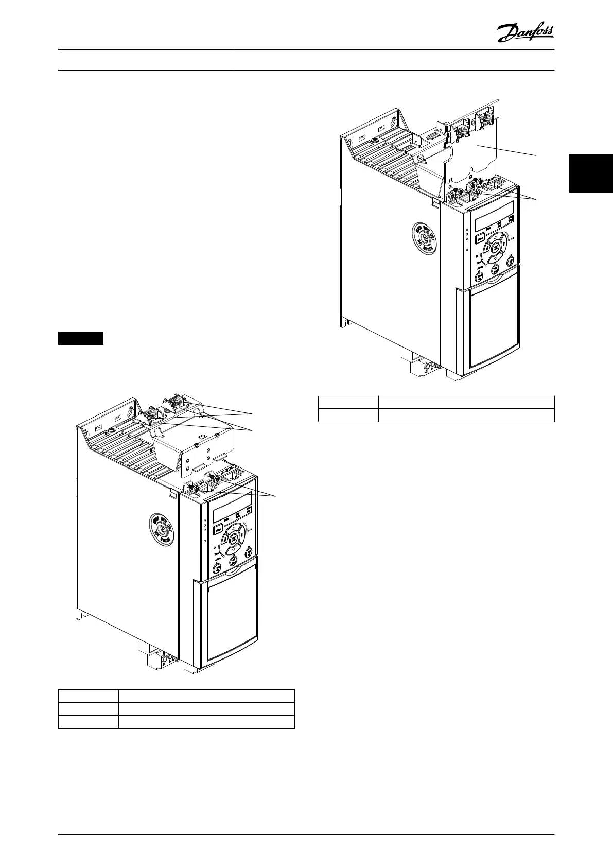
2. Optional: Mount the vertical decoupling plate as
follows:
2a Remove the 2 mechanical springs and 2
metal clamps from the horizontal plate.
2b Mount the mechanical springs and
metal clamps on the vertical plate.
2c Fasten the plate with 2 screws, as shown
in Illustration 3.5. Tightening torque 0.7–
1.0 Nm.
NOTICE
If the IP21 top cover is used, do not mount the vertical
decoupling plate, because its height aects the proper
installation of the IP21 top cover.
1 Mechanical springs
2 Metal clamps
3 Screws
Illustration 3.4 Fasten the Horizontal Decoupling Plate with
Screws
1 Vertical decoupling plate
2 Screws
Illustration 3.5 Fasten the Vertical Decoupling Plate with
Screws
Both Illustration 3.4 and Illustration 3.5 show PROFINET
sockets. The actual sockets are based on the type of the
control cassette mounted on the frequency converter.
3. Push the PROFIBUS/PROFINET/CANopen/Ethernet
cable connectors into the sockets in the control
cassette.
4. 4a Place the PROFIBUS/CANopen cables
between the spring-loaded metal
clamps to establish mechanical
xation
and electrical contact between the
screened sections of the cables and the
clamps.
4b Place the PROFINET/Ethernet cables
between the spring-loaded metal
clamps to establish mechanical xation
between the cables and the clamps.
Mechanical Installation Operating Instructions
MG07A102 Danfoss A/S © 11/2015 All rights reserved. 9
3 3

 Loading...


