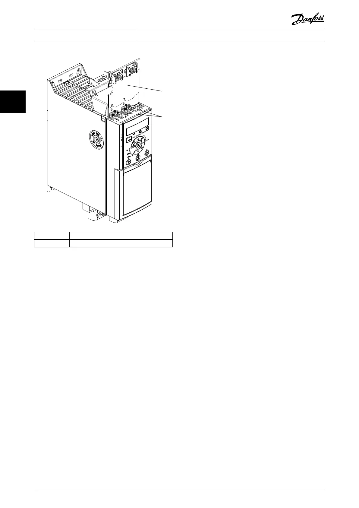
1 Vertical decoupling plate
2 Screws
Illustration 3.6 Fasten the Vertical Decoupling Plate with
Screws
Both Illustration 3.5 and Illustration 3.6 show Ethernet based
connectors (RJ45). The actual connector type depends on
the selected eldbus variant of the frequency converter.
3. Ensure proper wiring of the
eldbus cables
(PROFIBUS/CANopen) or push the cable
connectors (RJ45 for PROFINET/POWERLINK/
Ethernet/IP) into the sockets in the control
cassette.
4. 4a Place the PROFIBUS/CANopen cables
between the spring-loaded metal
clamps to establish mechanical xation
and electrical contact between the
shielded sections of the cables and the
clamps.
4b Place the PROFINET/POWERLINK/
Ethernet/IP cables between the spring-
loaded metal clamps to establish
mechanical xation between the cables
and the clamps.
Mechanical Installation
VLT
®
Midi Drive FC 280
12 Danfoss A/S © 10/2017 All rights reserved. MG07A402
33

 Loading...


