1.4.2 Block Diagram of the Frequency
Converter
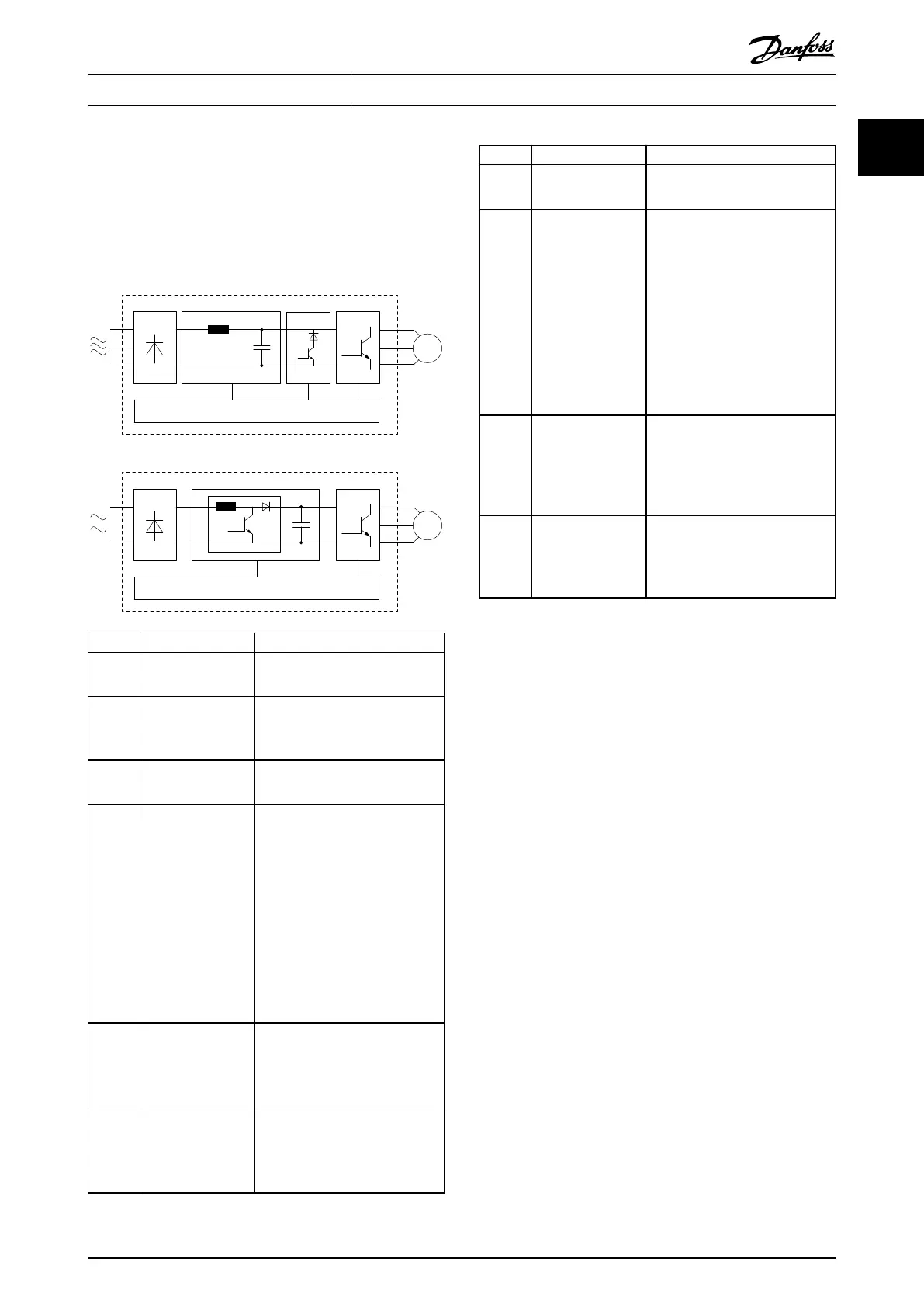
Illustration 1.1 is a block diagram of the internal
components of the frequency converter.
M
7
63
4
5
21
8
10
130BE200.12
M
7
63
4
5
21
8
9
T2/T4
S2
Area Component Functions
1 Mains input
•
AC mains supply to the
frequency converter.
2 Rectier
•
The rectier bridge converts
the AC input to DC current to
supply inverter power.
3 DC bus
•
Intermediate DC-bus circuit
handles the DC current.
4 DC reactor
•
Filters the intermediate DC
circuit current.
•
Provides mains transient
protection.
•
Reduces the root mean square
(RMS) current.
•
Raises the power factor
reected back to the line.
•
Reduces harmonics on the AC
input.
5 Capacitor bank
•
Stores the DC power.
•
Provides ride-through
protection for short power
losses.
6 Inverter
•
Converts the DC into a
controlled PWM AC waveform
for a controlled variable
output to the motor.
Area Component Functions
7 Output to motor
•
Regulated 3-phase output
power to the motor.
8 Control circuitry
•
Input power, internal
processing, output, and motor
current are monitored to
provide ecient operation
and control.
•
User interface and external
commands are monitored and
performed.
•
Status output and control can
be provided.
9 PFC
•
Power factor correction
changes the waveform of
current which is drawn by the
frequency converter to
improve the power factor.
10 Brake chopper
•
Brake chopper is used in the
DC intermediate circuit to
control DC voltage when the
load feeds energy back.
Illustration 1.1 Example of Block Diagram for a Frequency
Converter
1.4.3 Enclosure Sizes and Power Ratings
For enclosure sizes and power ratings of the frequency
converters, refer to chapter 9.9 Enclosure Sizes, Power
Ratings, and Dimensions.
1.4.4 Safe Torque O (STO)
The VLT
®
Midi Drive FC 280 frequency converter supports
Safe Torque O (STO). See chapter 6 Safe Torque O (STO)
for details about the installation, commissioning,
maintenance, and technical data of STO.
Introduction Operating Guide
MG07A402 Danfoss A/S © 10/2017 All rights reserved. 5
1 1

 Loading...


