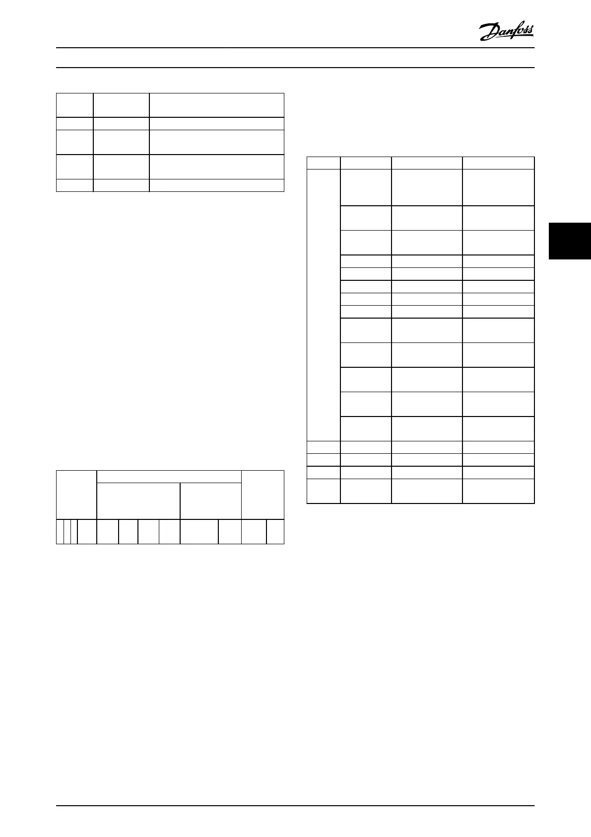
Master
SAP
Slave SAP Description
50 (32H) 49 (31H) Master Class 2: Initiate request
50 (32H) 0..48 (0..30H) Master Class 2: Abort, read, write,
data transfer
51 (33H) 50, 51 (32H,
33H)
Master Class 2: Alarm
51 (33H) 51 (33H) Master Class 2: Read, write
Table 5.2 Service Access Points (SAP)
5.2.6 DP-V1 Features for Parameter Access
This section describes how to use DP-V1 for accessing
frequency converter parameters.
The standard PROFIBUS DP-V1 read and write services are
not sucient for accessing the many parameters and
attributes in the frequency converter. For this reason, the
PROFIdrive parameter channel is dened. Using this
parameter read/write is performed by addressing a single
DP-V1 object in the frequency converter as shown in the
example, Table 5.3.
For a detailed description of the DP-V1 command handling,
refer to the PROFIBUS DP-V1 Design Guide.
Example
Slot=0
Index=47
PROFIBUS
telegram
header
Data unit PROFIBUS
telegram
trailer
DP-V1
command/response
PROFIdrive V3.0
parameter
channel
DU
0
DU
1
DU
2
DU
3
Req./Res.
Header
Data
Table 5.3 General Structure for Telegram
Use the DP-V1 command/response part for the standard
DP-V1 read/write on slot 0, index 47 data block.
Use the PROFIdrive V3 parameter channel to access
specic
parameter data in the frequency converter.
5.2.7 DP-V1 Read/Write Services
Table 5.4 shows the content of the DP-V1 command/
response headers and their possible attributes.
DU byte Value Meaning Specied
0 Function
number
0x48
Idle REQ, RES –
0x51 Data transport
REQ, RES
–
0x56 Resource manager
REQ
–
0x57 Initiate REQ, RES –
0x58 Abort REQ –
0x5C Alarm REQ, RES –
0x5E Read REQ, RES –
0x5F Write REQ, RES –
0xD1 Data transport
negative response
–
0xD7 Initiate negative
response
–
0xDC Alarm negative
response
–
0xDE Read negative
response
–
0xDF Write negative
response
–
1 Always zero Slot number DP-V1
2 47 Index DP-V1
3 xx Data length DP-V1
4..n User data PNO drive prole
V3.0
Table 5.4 DP-V1 Command/Response Headers
5.2.8 DP-V1 Acyclic Parameter Channel
Use the PROFIdrive parameter channel for read and write
access to parameter values and attributes.
•
Parameter values of simple variable, array, and
visible string.
•
Parameter description elements such as type and
minimum/maximum value.
•
Descriptive text for parameter values.
•
Access to multiple parameters in 1 telegram is
also possible.
Table 5.5 shows the structure of the PROFIdrive parameter
channel.
Parameter Access Programming Guide
MG37G202 Danfoss A/S © 01/2016 All rights reserved. 27
5 5

 Loading...


