23
www.Daniel.com
USER MANUAL
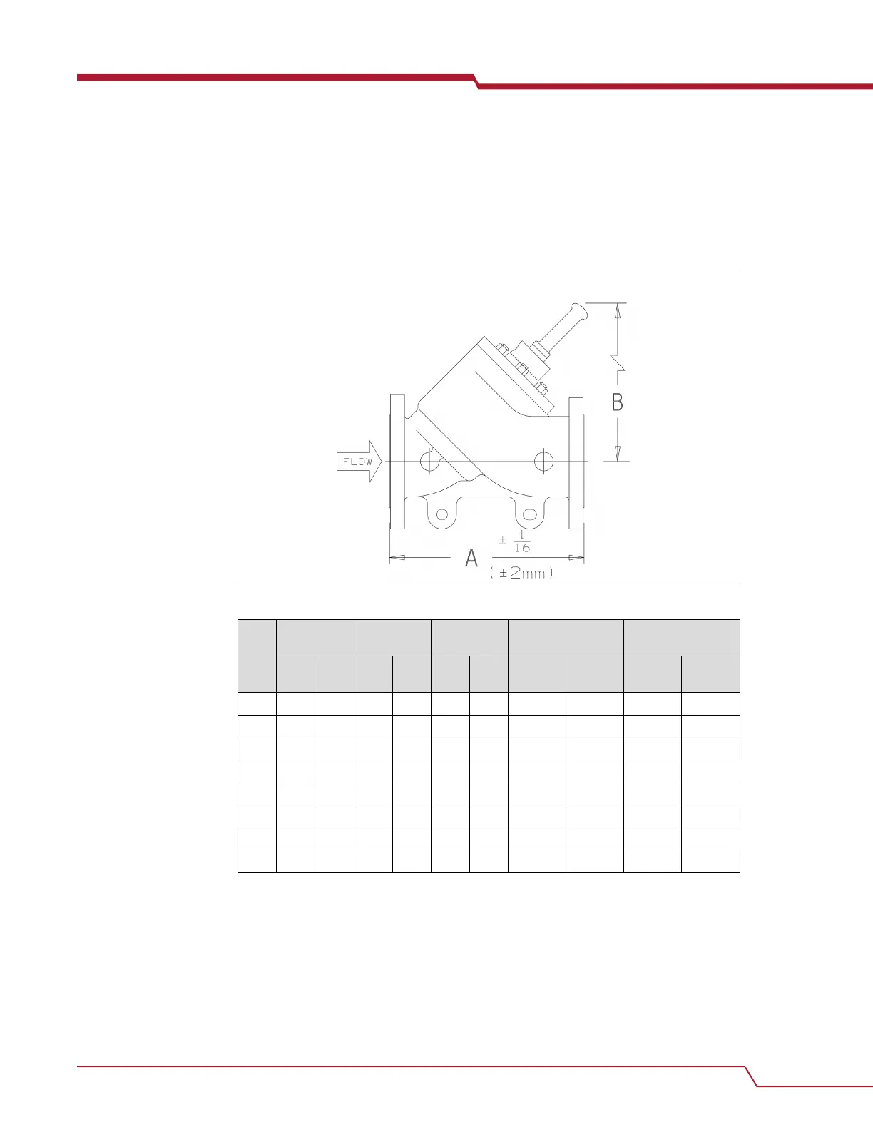
2.2.3 Minimum clearances for installation, operation and
maintenance
For certified prints, consult the factory.
Figure 2-2: Dimensions of the control valve
Table 2-4: Weight and volume table for the control valve (Approximate)
Size
(inch
es)
150 lb.
(ANSI)
300 lb.
(ANSI)
600 lb.
(ANSI)
150-300 lb.
(ANSI)
600 lb.
(ANSI)
lbs. Kg. lbs. Kg. lbs. Kg. Cubic
feet
Cubic
meters
Cubic
feet
Cubic
meters
2 55 25 60 27 100 45 1.66 0.047 1.79 0.051
3 95 43 105 48 150 68 2.36 0.067 2.5 0.071
4 115 52 140 64 205 93 2.51 0.071 3.13 0.089
6 210 95 250 113 400 181 4.84 0.137 6.07 0.172
8 400 181 465 211 725 329 8.94 0.253 9.96 0.283
10 640 290 700 318 1170 531 12.08 0.342 15.13 0.428
12 1040 472 1251 567 1820 826 20.25 0.573 21.94 0.621
16 CF CF CF CF CF CF 39.53 1.119 42.17 1.194
CF = consult factory
User manual Operating conditions and specifications
P/N 3-9008-553 November 2020
User manual 25