156
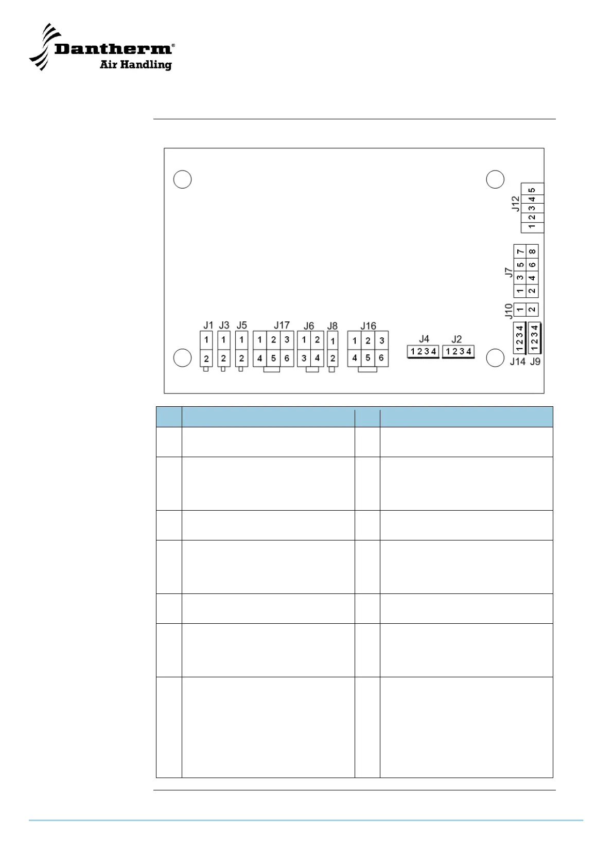
Schéma électrique
Ce schéma électrique correspond à HCV 3 et HCV 5 :
L – 230 V CA +/-15 %, 50/60 Hz
N – 230 V CA +/-15 %, 50/60 Hz
Commande du ventilateur
d'extraction
Tacho 1
PWM 1
10 V CC
0 V
Alimentation du ventilateur
d'extraction
L – 230 V CA +/-15 %, 50/60 Hz
N – 230 V CA +/-15 %, 50/60 Hz
Commande du ventilateur
d'alimentation
Tacho 2
PWM 2
10 V CC
0 V
Alimentation du ventilateur
d'alimentation
L – 230 V CA +/-15 %, 50/60 Hz
N – 230 V CA +/-15 %, 50/60 Hz
Sortie d'alimentation CA dérivée
L – Marche avant
L – Marche arrière
N – Cavalier
NC
T1 – NTC – 2 kΩ @ 25 °C
T1 – NTC – 2 kΩ @ 25 °C
T2 – NTC – 2 kΩ @ 25 °C
T2 – NTC – 2 kΩ @ 25 °C
T3 – NTC – 2 kΩ @ 25 °C
T3 – NTC – 2 kΩ @ 25 °C
T4 – NTC – 2 kΩ @ 25 °C
T4 – NTC – 2 kΩ @ 25 °C
Suite à la page suivante
 Loading...