STXC2 User’s guide
Version 2.0
2 of 30
1. General.
The control system is based on the following control units:
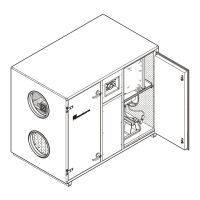
A STXC2 control circuit board that is mounted in the ventilation unit.
A STPT circuit board with a two-channel pressure sensor. It is mounted in the ventilation unit.
A STCU wall mounted MMI (Man Machine Interface).
A STLD wall mounted flow chart with LED’s (option).
A STIO circuit board for connection to a BMS (Building Management System) (option).
A single wire system (serial) communication) connects the circuit boards.
1.1 Control circuit board STXC2.
The STXC2 control circuit board and the two-channel pressure circuit board STPT2 give complete
control of air temperature and air volume by measuring and regulating the incoming signals (data).
The control of the air volume set point is displayed in m³/h, and keeps the air volume constant
independent of the duct pressures.
Regulating the amount of energy recovery by speed control of the heat wheel or, controlling the by-
pass damper in an air-to-air plate heat exchanger controls the temperature.
The active part of the temperature control is based on a plug connection on the ventilation unit. The
plug gives the possibility of connecting an external electric or water (LPHW) heating coil.
The ventilation system can also control a Chilled water or DX cooling coil.
There is the option of pre-cooling at night in the summer periods and reduction of ambient air
introduction in extreme cold winter periods.
1.1.1 Function switch.
The ventilation unit is equipped with a function switch that has the positions AUTO, OFF and
MAN (Manual).