14
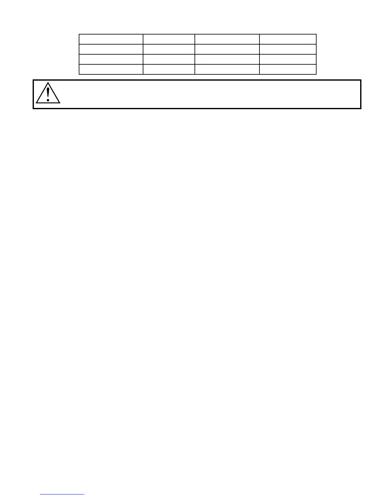
GHFC-74 2-1/8” O.D. GHFC-264 2-5/8” O.D.
GHFC-84 2-5/8” O.D. GHFC-281 2-5/8” O.D.
GHFC-99 2-5/8” O.D. GHFC-310 2-5/8” O.D.
GHFC-106 2-1/8” O.D. GHFC-352 2-5/8” O.D.
Models GHFC-200 and larger are double-wide units. Although the header connection for
each section is 2-5/8”, each unit comes with a factory provided header manifold kit with
3-1/8”eldconnections.
2.3 Auxiliary Chilled Water/Energy Saver Coil Piping
Units with Auxiliary Chilled Water cooling coil require a separate source of chilled water. These
chilled water connection sizes will be equal to the condenser water connection sizes on the chart in
Section 2.2.2. Units with an Energy Saver cooling coil have shared piping with the condenser sup-
ply and therefore do not require a separate water source.
All chilled water pipes have a cap installed on the end of the pipe for factory pressure testing of the
system. These caps need to be removed before installing the water piping to the unit. Use a tube
cutter for smaller pipes and reciprocating saw with a metal cutting blade for larger pipes or if there is
a clearance problem. All connections need to be cleaned before connections are brazed together.
2.4 Condensate Drain Piping
Every indoor unit has a 3/4” copper stub provided for condensate removal. A union is recommended
attheeldconnectionwhichwillpermiteasydisconnectionfromtheunitforcleaning.
A trap should be built into the drain line to prevent air from backing up into the unit. Drain lines
should be pitched downward not less than 1/4” for each ten feet of horizontal run. Do not reduce
the size of the drain line.
Some applications have no convenient means of allowing a gravity drain. When required, a con-
densate pump can be used. Condensate pumps are either factory mounted or shipped loose. Fac-
tory mounted condensate pumps do not require a separate power source.
Condensatepumps shipped loose (or eldprovided)typicallyrequireadedicated 110 volt power
source. Field pipe connections must be made to the pump discharge connection. A check valve
must be installed to prevent short cycling. See condensate pump electrical requirements in Section
3.9.
2.5 Humidier Piping
2.5.1 Steam Generator Humidier
ThestandardhumidierongForcesystemsisasteamgeneratortypewithdisposablecylinder.The
humidiermakeupwatershouldbebroughttothehumidierthroughtheeldconnectionopening
using1/4”coppertubing.Acompressionttingisprovidedatthehumidier.
A shutoff valve should be provided outside the air conditioner to allow disconnection for service.
An in-line water pressure regulator and strainer should be installed. Water pressure should be set
between 20 and 80 PSI.
 Loading...
